Antenna module and related device

An antenna module and antenna technology, applied in measuring devices, radio wave measuring systems, and reradiation of sound waves, can solve problems such as low accuracy of proximity detection and inability to distinguish self-capacitance changes

Inactive Publication Date: 2022-04-15
SHENZHEN XIHUA TECH CO LTD
View PDF0 Cites 0 Cited by
  • Summary
  • Abstract
  • Description
  • Claims
  • Application Information

AI Technical Summary

Problems solved by technology

[0004] However, the antenna used in mobile communication equipment will also cause a large change in self-capacitance when the temperature changes. As a result, when the self-capacitance method is used for detection, it is impossible to distinguish whether the self-capacitance change is caused by the proximity of the object or the temperature change.
Therefore, there is a problem that the accuracy of the existing object proximity detection based on the change of the antenna self-capacitance is low

Method used


Image

  • Antenna module and related device
  • Antenna module and related device
  • Antenna module and related device

Examples


Embodiment 1

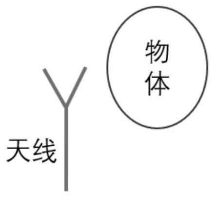
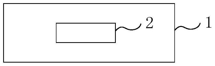
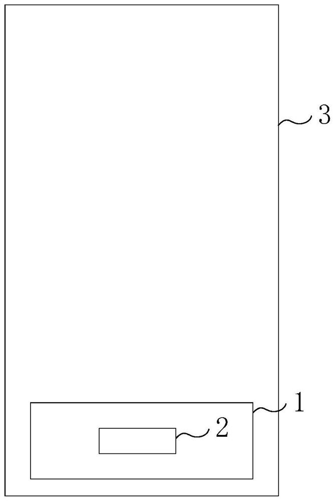
[0090] In this application, an embodiment is provided with an antenna module. figure 2 Distance figure 2 It is a schematic structural diagram of an antenna module provided by the embodiment of the present application, including: antenna 1 and at least one sensing electrode 2; wherein the sensing electrode 2 is located in an area in which the antenna 1 is electromagnetically shielded in at least one direction. When the external human body is close to the antenna 1, the antenna 1 can partition the electric field line between the outer body and the sensing electrode 2. For example, the antenna 1 can partition an electric field line in the predetermined ratio between the external human body and the sensing electrode 2. Among them, the predetermined ratio is, for example, 70%, 75%, 80%, 85%, 90%, or 95%. Preferably, the antenna 1 can, for example, completely or close to an electric field line between the external human body and the sensing electrode 2. When the antenna 1 can partition ...

Embodiment 2

[0109] The second embodiment of the present application provides a self-capacitance change detecting device of antenna 1, which can be applied to an antenna module provided by an embodiment, and the structure of the self-capacitance change detecting device. Figure 5 Distance Figure 5 It is a schematic structural diagram of an antenna self-capacitance change detecting apparatus provided by the embodiment of the present application, including an antenna self-contraction module 101, a sensing electrode self-container detecting module 102, a first determining module 103, and a second determining module 104.

[0110] The antenna self-contained module 101 is used to obtain the total amount of self-capacitance change of the antenna 1.

[0111] Optionally, for example, but not limited thereto, the antenna self-contained module 101 is used to acquire the total amount of self-capacitance change with respect to the reference time relative to the reference time.

[0112] The sensing electrode...

Embodiment 3

[0138] The third embodiment of this application provides a proximity detecting device, which can be applied to an antenna module provided by an embodiment, and the structure of the proximity detecting device such as Figure 8 Distance Figure 8 It is a schematic structural diagram of a proximity detecting device provided by the embodiment of the present application, including an antenna self-contraction module 201, a sensing electrode self-container 202, a first determination module 203, and a third determining module 204.

[0139] The antenna self-contraction module 201 is used to acquire the total amount of self-capacitance variation of the antenna 1.

[0140] Optionally, the antenna self-contraction module 201 is used to acquire the total amount of self-capacitance variation of the antenna 1.

[0141] The sensing electrode self-container detecting module 202 is used to acquire the total amount of self-capacitance variation of the sensing electrode 2.

[0142] Optionally, the sens...


PUM


Abstract

The embodiment of the invention provides an antenna module and a related device. The antenna module comprises an antenna and at least one sensing electrode, and the sensing electrode is located in an area which can be electromagnetically shielded by the antenna in at least one direction. The method comprises the following steps: acquiring a total self-capacitance change amount of a sensing electrode through a related device applied to an antenna module, and determining a first self-capacitance change amount of an antenna caused by temperature change according to the total self-capacitance change amount of the sensing electrode and a preset self-capacitance change proportionality coefficient; and determining a difference value between the total self-capacitance change amount of the antenna and the first self-capacitance change amount as a second self-capacitance change amount of the antenna caused by approaching of the object. According to the antenna self-capacitance change detection method, the antenna self-capacitance change caused by object approaching can be accurately determined, so that whether an object approaches or not is accurately judged, and the transmitting power of the antenna is better controlled and adjusted.

Description

Technical field [0001] The present application relates to the field of capacitive detection, and in particular, to an antenna module and related devices. Background technique [0002] Electromagnetic absorption ratio or specific absorption rate (SPECific ABSORPTION RATE, SAR) is a basic limit of electromagnetic radiation of radio equipment, in the process of radio equipment, especially when there is a human body, it is necessary to reduce SAR to a suitable level, This makes the radio equipment compliant with the SAR standard to reduce the effects of radiation on the human body. [0003] Taking the mobile communication device as an example, the self-capacity change of the antenna can be determined by the self-compressive change in the mobile communication device, and when it is judged that the human body is approaching, the transmission power of the antenna can be appropriately reduced to make mobile communication. The device meets SAR restriction requirements. [0004] However, t...

Claims


Application Information

Patent Timeline
Patent Type & Authority Applications(China)
IPC IPC(8): G01V3/00G01R27/26
Inventor 王洁陈曦
Owner SHENZHEN XIHUA TECH CO LTD
Why Eureka
Try Eureka