Follow-up loading device for movable airfoil of aircraft

A technology of dynamic loading and dynamic airfoil, which is applied in the direction of measuring devices, machine/structural component testing, instruments, etc., can solve the problem of limiting the degree of freedom and stretching efficiency of the skin, and the loading method cannot fully verify the law of intelligent structure changes. It is difficult to accurately simulate the mutual influence of the real load history of the movable airfoil, so as to meet the requirements of engineering tests

Active Publication Date: 2022-05-17
CHINA AIRPLANT STRENGTH RES INST
View PDF6 Cites 3 Cited by
  • Summary
  • Abstract
  • Description
  • Claims
  • Application Information

AI Technical Summary

Problems solved by technology

[0002] Due to the application of intelligent structure and skin, the camber of the aircraft wing surface changes greatly and the aerodynamic efficiency is higher. The real-time simulation of aerodynamic load loading during the trajectory of the aircraft has become a key research direction. Traditionally, tapes or tension pads are used. The fixed loading method of the structure often limits the degree of freedom and stretching efficiency of the skin. During the test, additional constraints are added to the structure. The loading method cannot fully verify the changing law of the intelligent structure, and it is difficult to accurately simulate the movable airfoil. The actual loading history of the system as a whole during the flight of the aircraft and the interaction between the structure and the motion mechanism during the loading process

Method used


Image

  • Follow-up loading device for movable airfoil of aircraft
  • Follow-up loading device for movable airfoil of aircraft
  • Follow-up loading device for movable airfoil of aircraft

Examples


Embodiment Construction

[0025] In order to make the purpose, technical solution and advantages of the application more clear, the technical solution in the embodiment of the application will be described in more detail below in conjunction with the drawings in the embodiment of the application. In the drawings, the same or similar reference numerals denote the same or similar elements or elements having the same or similar functions throughout. The described embodiments are some, but not all, embodiments of the application. The embodiments described below by referring to the figures are exemplary, and are intended to explain the present application, and should not be construed as limiting the present application. Based on the embodiments in this application, all other embodiments obtained by persons of ordinary skill in the art without creative efforts fall within the protection scope of this application.

[0026] It should be understood that technical terms that may be involved in the description o...


PUM


Abstract

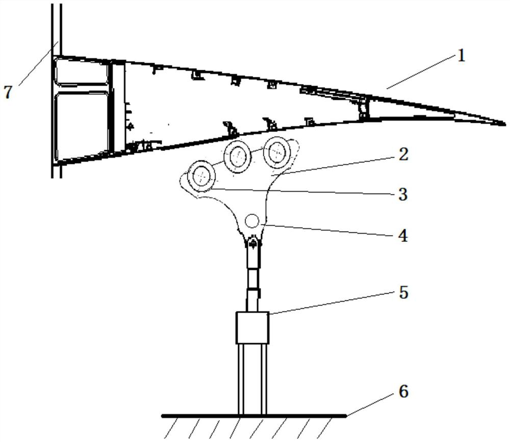
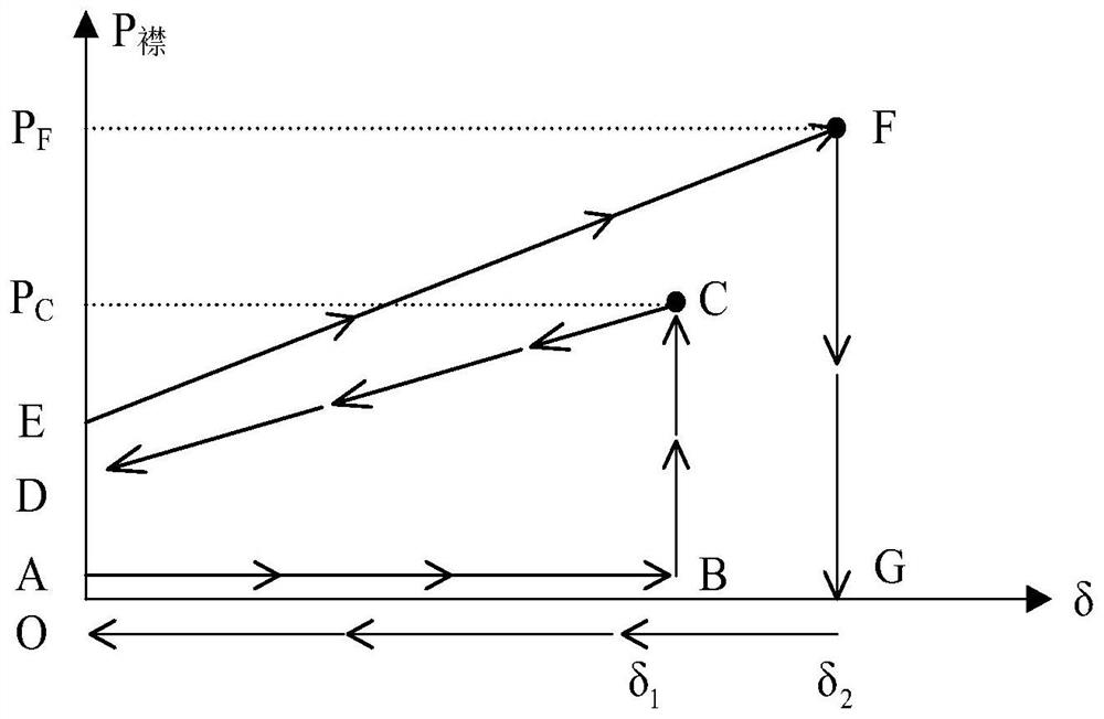
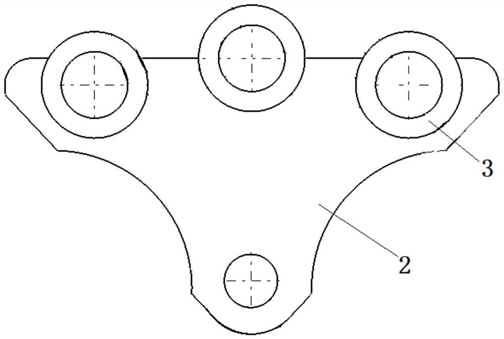
The invention belongs to the technical field of aircraft motion mechanism tests, and particularly relates to a follow-up loading device for a movable airfoil of an aircraft, and the device comprises a test piece fixing device which is used for fixing the movable airfoil; the loading actuating cylinder is fixed on the terrace and is positioned at the bottom of the movable wing surface; the follow-up loading head is hinged with a loading rod of the loading actuating cylinder and can rotate around a hinged joint, in addition, at least three loading rollers are embedded at the top end of the follow-up loading head, and the outer wheel surfaces of the loading rollers are in linear contact with the movable wing surface; the driving device is used for driving the movable airfoil to deflect; the angle sensor is used for detecting the deflection angle of the movable airfoil in real time; and the control system is used for controlling the movable wing surface and the loading actuating cylinder. According to the follow-up loading device for the movable airfoil of the aircraft, follow-up loading of the movable airfoil movement mechanism is achieved by adjusting the self-adaptive follow-up loading head, and the loading problem of a flap and slat structure system in all flight attitudes can be accurately reflected.

Description

technical field [0001] The application belongs to the technical field of aircraft motion mechanism testing, and in particular relates to a follow-up loading device for a movable wing surface of an aircraft. Background technique [0002] Due to the application of intelligent structure and skin, the camber of the aircraft wing surface changes greatly and the aerodynamic efficiency is higher. The real-time simulation of aerodynamic load loading during the trajectory of the aircraft has become a key research direction. Traditionally, tapes or tension pads are used. The fixed loading method of the structure often limits the degree of freedom and stretching efficiency of the skin. During the test, additional constraints are added to the structure. The loading method cannot fully verify the changing law of the intelligent structure, and it is difficult to accurately simulate the movable airfoil. The real loading process of the system as a whole during the flight of the aircraft and...

Claims


Application Information

Patent Timeline
Patent Type & Authority Applications(China)
IPC IPC(8): G01M13/00
CPCG01M13/00
Inventor 庞宝才臧伟锋沈子实陈先民李磊李珊山李耀
Owner CHINA AIRPLANT STRENGTH RES INST
Why Eureka
Try Eureka