Follow-up loading device and method based on industrial robot system

An industrial robot and follow-up loading technology, which is applied in the direction of measuring devices, optical devices, instruments, etc., can solve the problem of large wing deformation and achieve the effect of follow-up loading

Pending Publication Date: 2022-05-13
AVIC BEIJING CHANGCHENG AVIATION MEASUREMENT & CONTROL TECH INST +2
View PDF8 Cites 1 Cited by
  • Summary
  • Abstract
  • Description
  • Claims
  • Application Information

AI Technical Summary

Problems solved by technology

However, the main problem in the current wing static test is that due to the large deformation of the wing, there is often a cer

Method used


Image

  • Follow-up loading device and method based on industrial robot system
  • Follow-up loading device and method based on industrial robot system
  • Follow-up loading device and method based on industrial robot system

Examples


Embodiment 1

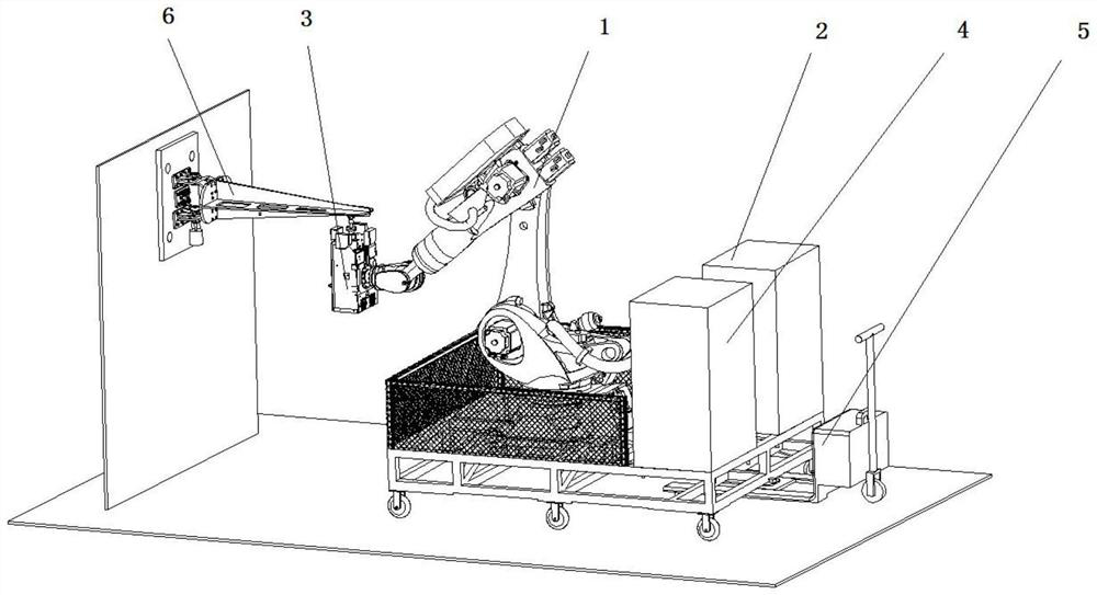
[0057] refer to figure 1 , The follow-up loading device based on the industrial robot system provided in this embodiment at least includes a control terminal 4, a follow-up loading end effector 3 and a normal direction measurement sensor.

[0058] The follow-up loading end effector 3 is installed on the industrial robot system.

[0059] The normal direction measuring sensors include a first group of ranging sensors and a second group of ranging sensors; the first group of ranging sensors and the second group of ranging sensors both include two and are symmetrically distributed on the loading end of the follow-up loading end effector 3 The distance-measuring sensor above, and the relationship between the connection line between the two distance-measuring sensors in the first group of distance-measuring sensors and the connection line between the two distance-measuring sensors in the second group of distance-measuring sensors is a vertical relationship.

[0060] The normal dire...

Embodiment 2

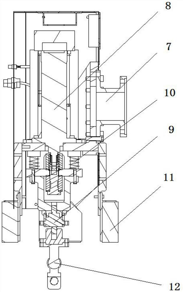
[0096] A kind of follow-up loading method based on the industrial robot system provided by this embodiment is to calculate the normal deviation value of the loaded point through the data measured by the normal measurement sensor 11, and then transmit it to the robot control cabinet 2 through the control terminal 4, The robot control cabinet 2 controls the robot body 1 and the follow-up loading end effector 3 to adjust the attitude according to the normal deviation value, and at the same time, the electric cylinder 8 on the follow-up loading end effector 3 is based on the force measured in real time by the tension and pressure sensor 9, Adjust the loading force output by the electric cylinder 8 to keep the loading force constant.

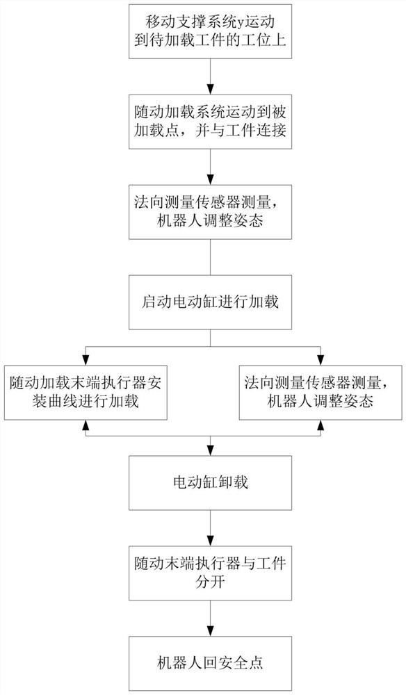
[0097] Reference attached figure 2 , the follow-up loading method specifically includes the following steps:

[0098] Step 1: The mobile support system drives the robot body, robot control cabinet, control terminal, etc. to the station where the work...


PUM


Abstract

The invention discloses a follow-up loading device and method based on an industrial robot system. The follow-up loading device at least comprises a control end, a follow-up loading end effector and a normal measurement sensor. The follow-up loading end effector is mounted on the industrial robot system; the normal measurement sensor is used for acquiring distance information between a loading end and a loaded point; the control end is used for calculating a normal deviation value of the loaded point based on the distance information between the loading end and the loaded point; based on the normal deviation value of the loaded point, the industrial robot system is controlled to adjust the loading direction of the follow-up loading end effector, so that the loading direction coincides with the normal direction of the loaded point, and the problems that due to large deformation, the loaded point is not perpendicular to the chord plane of the airfoil, the loading direction is changed, and the larger the deformation is, the larger the loading direction is, the larger the loading direction is, are solved. And the angular deviation of the load is larger.

Description

technical field [0001] The invention relates to the technical field of test and test, in particular to a follow-up loading device and method based on an industrial robot system. Background technique [0002] High-endurance UAVs will be widely used in the military and civilian fields in the future. In order to take the lead in reconnaissance and collection, and take into account the strike function, this type of UAV needs to have high-altitude, long-duration and large-load capabilities. The UAV wing is required to have a considerable aspect ratio, but due to the extensive use of composite materials in UAVs, the deformation of such wings is exacerbated. The surface of the wing during flight is mainly affected by the aerodynamic load, and the load direction is always the normal direction of the wing surface. Therefore, in order to better simulate the loading of the wing in the wing structural strength test, the most accurate method is The loading direction can be adjusted and ...

Claims


Application Information

Patent Timeline
IPC IPC(8): G01N3/08G01B11/14
CPCG01N3/08G01B11/14G01N2203/0003G01N2203/0019G01N2203/0075G01N2203/0676G01N2203/0682Y02P90/02
Inventor 张明华崔静静郭强贺喜鹏张玉如李明
Owner AVIC BEIJING CHANGCHENG AVIATION MEASUREMENT & CONTROL TECH INST
Why Eureka
Try Eureka