
Method for evaluating hail impact resistance of tower type solar heliostat structure

A tower-type solar energy and heliostat technology, which is applied in data processing applications, instruments, design optimization/simulation, etc., can solve the problems of not considering the hail load, the structural design of the heliostat is too conservative, and cannot be designed in a targeted manner. The effect of ensuring normal and stable use and avoiding the risk of hail disasters

Pending Publication Date: 2022-06-03
WUHAN UNIV OF TECH
View PDF0 Cites 0 Cited by
  • Summary
  • Abstract
  • Description
  • Claims
  • Application Information

AI Technical Summary

Problems solved by technology

[0003] For heliostats, hail will not only threaten the safety of the structure itself, but also reduce its concentrating efficiency, thereby affecting the performance of the entire solar thermal power generation system
At present, the research on heliostats mainly focuses on the dynamic characteristics and wind-induced response of the heliostat itself. The design basis for the heliostat structure is the general design standard, and the hail load is not considered.
However, the damage mode and dynamic catastrophe of heliostats under the action of hail still need to be thoroughly studied.
That is to say, the current existing design basis cannot fully meet the requirements of anti-hail, and cannot be designed in a targeted manner. As a result, for areas with high frequency of hail and large size of hail, the existing structural design basis of heliostats cannot fully meet the requirements. Anti-hail requirements for heliostats, and for areas with low frequency of hail and small size of hailstones, the existing structural design basis for heliostats may lead to overly conservative structural design of heliostats, resulting in additional economic costs

Method used


Image

  • Method for evaluating hail impact resistance of tower type solar heliostat structure
  • Method for evaluating hail impact resistance of tower type solar heliostat structure
  • Method for evaluating hail impact resistance of tower type solar heliostat structure

Examples


Embodiment Construction

[0043] The technical solutions in the embodiments of the present application will be clearly and completely described below in conjunction with the drawings in the embodiments of the present application.

[0044]In the following introduction, the terms "first" and "second" are only used for the purpose of description, and should not be understood as indicating or implying relative importance. The following introduction provides multiple embodiments of the present application, and different embodiments can be replaced or combined and combined, so the present application can also be considered to include all possible combinations of the same and / or different embodiments described. Thus, if one embodiment contains features A, B, C, and another embodiment contains features B, D, then the application should also be considered to include all other possible combinations containing one or more of A, B, C, D Although this embodiment may not be clearly written in the following content. ...


PUM


Abstract

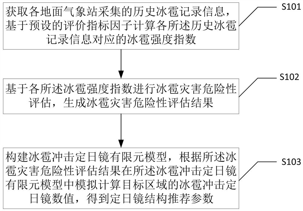
The invention discloses a method for evaluating the hail impact resistance of a tower type solar heliostat structure, and the method comprises the steps: obtaining historical hail record information collected by each ground weather station, and calculating a hail intensity index corresponding to each piece of historical hail record information based on a preset evaluation index factor; performing hail disaster risk assessment based on each hail intensity index to generate a hail disaster risk assessment result; and constructing a hail impact heliostat finite element model, simulating and calculating a hail impact heliostat numerical value of the target area in the hail impact heliostat finite element model according to a hail disaster risk assessment result, and obtaining heliostat structure recommendation parameters. According to the method, numerical simulation of impact of hail on the heliostat is realized, and the structure parameters of the heliostat can be reasonably recommended according to evaluation results of different dangerous areas, so that hail disaster risks can be effectively avoided during operation of the heliostat, and normal and stable use of the heliostat is ensured.

Description

technical field [0001] The present application relates to the technical field of hail impact performance evaluation, in particular, to a method for evaluating the anti-hail impact performance of a tower solar heliostat structure. Background technique [0002] The heliostat is the most basic concentrating unit in the tower solar thermal power generation system and also accounts for the largest investment, accounting for about 50% of the total construction cost. In order to meet the requirements of the production process, solar thermal power stations are usually built in open areas with an annual sunshine rate of more than 90%. From the perspective of the total annual solar energy resources, the Qinghai-Tibet Plateau is the region with the richest solar energy resources in China, which meets the corresponding radiation resource requirements for the construction of large-scale solar power plants. At the same time, the special topography of the plateau and the instability of ne...

Claims


Application Information

Patent Timeline
IPC IPC(8): G06F30/20G06Q50/06
CPCG06F30/20G06Q50/06Y04S10/50
Inventor 吉柏锋熊倩
Owner WUHAN UNIV OF TECH
Learn More