Side beam hanging structure and railway vehicle
A side beam and hanging technology, which is applied in the field of rail vehicles, can solve the problems that the original beam hanging can not meet the needs, can not meet the requirements of light weight, and the installation method is complicated, so as to avoid changes in structural strength and process equipment, and manufacturing processes. The effect of strong sex and reducing labor intensity
Pending Publication Date: 2022-06-24
CRRC QINGDAO SIFANG CO LTD
View PDF0 Cites 0 Cited by
- Summary
- Abstract
- Description
- Claims
- Application Information
AI Technical Summary
Problems solved by technology
With the development requirements of vehicle weight and cost, especially for small-batch and multi-variety urban rail vehicle products, the original beam suspension cannot meet the demand, and the modularization and standardization of vehicle systems have become a development trend
[0004] The inventors found that the existing beam suspension needs to arrange functional components such as longitudinal beams, and the weight of the vehicle body is relatively large, which cannot meet the requirements of light weight; and the existing beam suspension is complicated to install when installing equipment under the vehicle, and the efficiency is low. Low and labor-intensive when installed under the vehicle
Method used
View moreImage
Smart ImageViewing Examples
Examples
Embodiment 2
[0063] This embodiment provides a rail vehicle including the above-mentioned side beam suspension structure.
Login to View More PUM
 Abstract
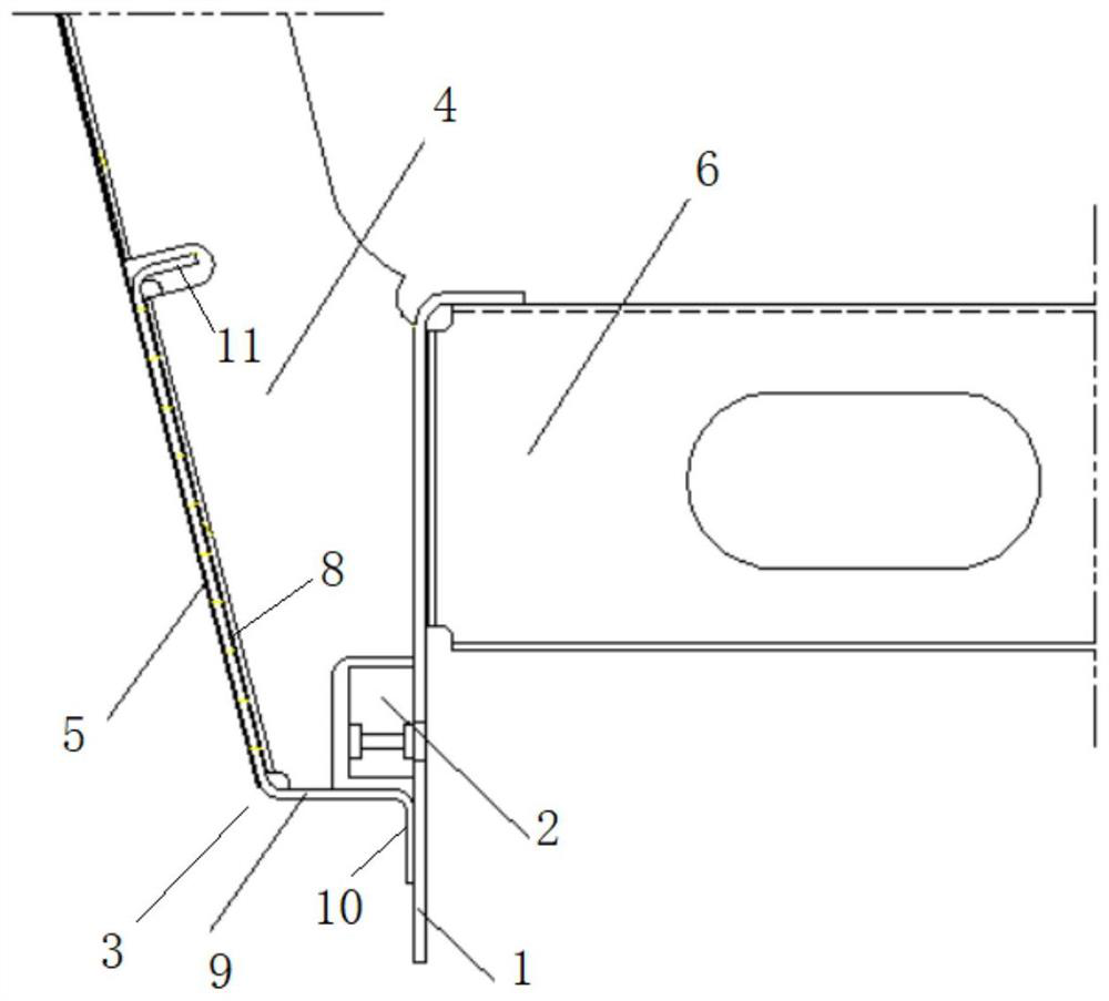
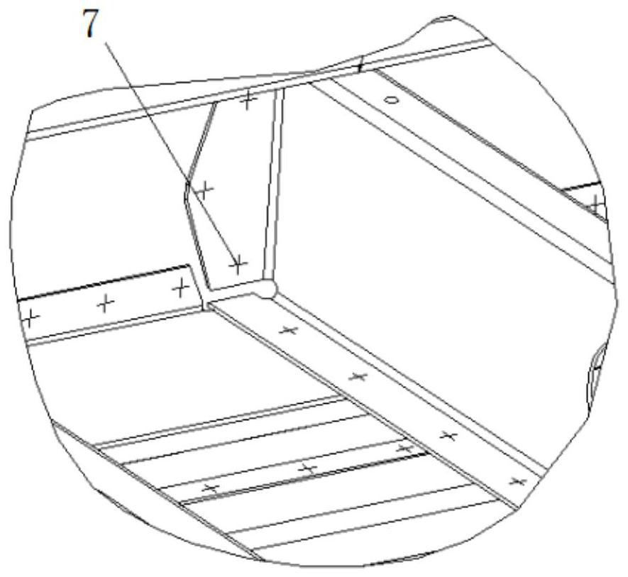
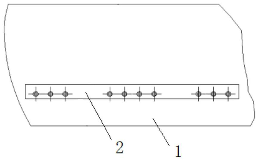
The invention discloses a boundary beam hanging structure and a railway vehicle, and belongs to the technical field of railway vehicles. The boundary beam hanging structure comprises an underframe cross beam, and the two ends of the underframe cross beam are fixedly connected with underframe boundary beams; a reinforcing beam is fixedly arranged on the outer side of the chassis boundary beam, and a plurality of hanging holes are formed in the reinforcing beam; the outer sides of the underframe boundary beams are further fixedly connected with the side wall boundary beams, the tops of the side wall boundary beams are bent and connected with the stand columns in a clamped mode, and the stand columns are fixedly connected with the outer sides of the underframe boundary beams. The hanging structure provides a way for overall installation of the under-vehicle equipment bin, and the installation efficiency of under-vehicle equipment of vehicle final assembly is improved.
Description
technical field [0001] The invention belongs to the technical field of rail vehicles, and in particular relates to a side beam hanging structure and a rail vehicle. Background technique [0002] The statements herein merely provide background related to the present invention and do not necessarily constitute prior art. [0003] In the development of various vehicle pedigrees in the rail passenger car industry, the installation of equipment under the car is mostly carried by beams. Considering the requirements of weight balance and the structural strength of the lifting point, it is necessary to arrange the position of the underframe beams according to the equipment layout, and additionally weld and install functional components such as longitudinal beams and reinforcing seats on the underframe. With the development requirements of vehicle weight and cost, especially for small-batch and multi-variety urban rail vehicle products, the original beam suspension cannot meet the d...
Claims
Login to View More Application Information
Patent Timeline
 Patent Type & Authority Applications(China)
IPC IPC(8): B61F1/08B61F1/14
CPCB61F1/08B61F1/14
Inventor 赵延强李刚卿田洪雷窦学利万里
Owner CRRC QINGDAO SIFANG CO LTD
Features
- R&D
- Intellectual Property
- Life Sciences
- Materials
- Tech Scout
- Unparalleled Data Quality
- Higher Quality Content
- 60% Fewer Hallucinations
Learn More Browse by: Latest US Patents, China's latest patents, Technical Efficacy Thesaurus, Application Domain, Technology Topic, Popular Technical Reports.
© 2025 PatSnap. All rights reserved.Legal|Privacy policy|Modern Slavery Act Transparency Statement|Sitemap|About US| Contact US: help@patsnap.com


