Shoulder support structure and method for correcting violin playing support position
A bracket structure and violin technology, applied to violins, musical instruments, stringed instruments, etc., can solve problems that are difficult or difficult for one person to complete easily
- Summary
- Abstract
- Description
- Claims
- Application Information
AI Technical Summary
Problems solved by technology
Method used
Image

Examples
no. 1 example
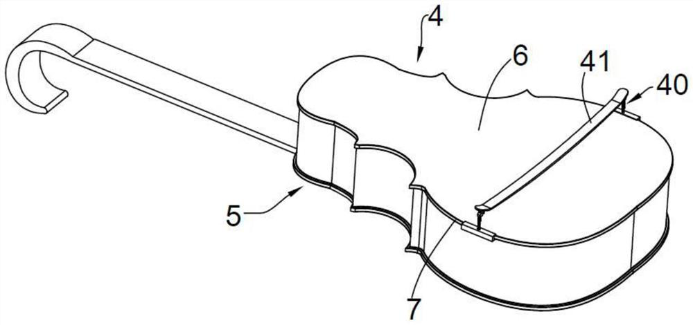
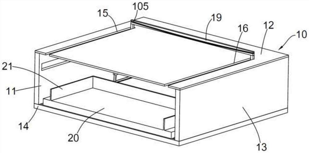
[0028] like Figure 3 to Figure 5 As shown, the present invention provides a shoulder support structure for calibrating the violin playing support position, which includes a box body structure 10, a carrying sliding bracket 20, a driving structure 30 and a shoulder support 40;
[0029] The box structure 10 has a side opening 11, a top panel 12, a side panel 13 and a bottom panel 14. The top panel 12 is provided with a first slot 15 and a second slot 16. The top panel 12 is provided with a first slot 15 and a second slot 16. A mounting block 17 is provided at the lower position of the plate body 12 , one side of the mounting block 17 is slidably arranged in the side plate 13 , the mounting block 17 has a notch 18 , and the mounting block 17 is There is a backrest board 19 at the rear position, the top of the backrest board 19 passes through the first insertion slot 15 and the second insertion slot 16 ; and the backrest passes between the first insertion slot 15 and the second i...
no. 2 example ;
[0037] like Image 6 and Figure 8 As shown, the bottom plate body 14 forms a chute structure 60 . The front and rear sides of the chute structure 60 are respectively provided with a first return spring 61 and a second return spring 62 . Both sides are slidably arranged in the chute structure 60 through a sliding block 63 , and one side of the sliding block 63 is connected to the first return spring 61 , and one end of the sliding block 63 has a driving block 64 , so The bottom of the flip plate 31 has a driving rod 65, one end of the second return spring 62 is connected with the driving rod 65, the middle of the flip board 31 is hinged on the connecting shaft 66, and the connecting shaft 66 is fixed on the side On the plate body 13, the upper side of the flip plate 31 has a snap ring 67, and the snap ring 67 is sleeved on the first sliding column 68 provided on the side of the mounting block 17. The mounting block 17 The side part is also provided with a second sliding colu...
no. 3 example ;
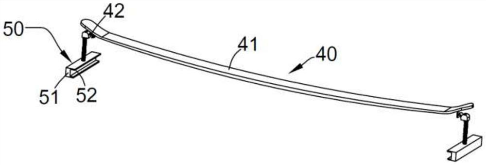
[0041] like Figure 5 As shown, preferably, the clamping member 50 has an adjusting screw 81 and an engaging portion 51, the engaging portion 51 is arranged at the bottom of the screw 81, and the engaging portion 51 has a mounting hole, and the engaging portion 51 has a mounting hole. The engaging portion 51 is rotatably sleeved on the screw rod 81 through the inner wall thread of the mounting hole.
[0042] When the engaging portion 50 is placed on the notch portion 18 of the mounting block 17 , the engaging portion 50 is rotated upward around the screw 81 in advance so that the bottom of the screw 81 forms an exposed portion, and the exposed portion is exposed. The part is inserted into the smooth socket or the smooth oblique arc socket fixed in the notch part 18 for stability; that is, when the engaging groove is matched with the arc edge, it is guided by the movement of the exposed part in the socket Stabilizing effect, when the engaging groove 52 of the engaging portion ...
PUM
 Abstract
Description
Claims
Application Information
 - R&D
- Intellectual Property
- Life Sciences
- Materials
- Tech Scout
- Unparalleled Data Quality
- Higher Quality Content
- 60% Fewer Hallucinations
Browse by: Latest US Patents, China's latest patents, Technical Efficacy Thesaurus, Application Domain, Technology Topic, Popular Technical Reports.
© 2025 PatSnap. All rights reserved.Legal|Privacy policy|Modern Slavery Act Transparency Statement|Sitemap|About US| Contact US: help@patsnap.com