Cooking equipment
A technology of cooking equipment and cooking cavity, which is applied in the direction of roaster/barbecue grid, kitchen utensils, household utensils, etc., can solve the problems of affecting the use experience of the oven, uneven temperature, single wind direction, etc., and achieves simple structure and uniform distribution. , the effect of large airflow coverage
- Summary
- Abstract
- Description
- Claims
- Application Information
AI Technical Summary
Problems solved by technology
Method used
Image

Examples
Embodiment 1
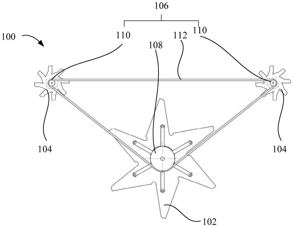
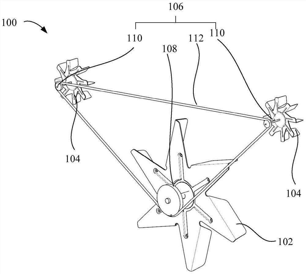
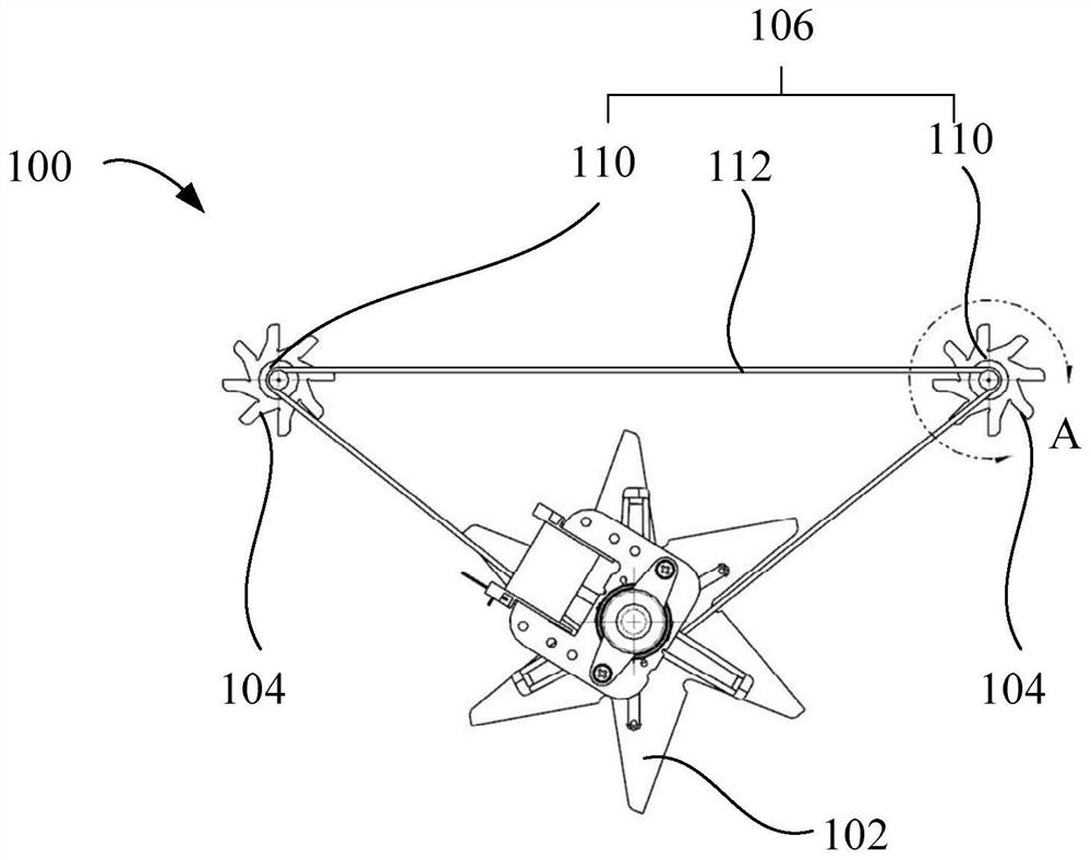
[0030] like figure 1 , figure 2 As shown, a cooking device 200 proposed in this embodiment includes a casing 202 and a fan assembly 100 disposed in the casing 202, so that under the action of the casing 202, the fan assembly can be protected, while the fan assembly 100 The airflow in the cooking cavity 204 can be driven to flow, so that the temperature in the cooking device 200 can be uniform. Specifically, the fan assembly 100 includes: a first impeller 102 and a plurality of second impellers 104, and between the first impeller 102 and the plurality of second impellers 104, there are a plurality of transmission assemblies 106, the first impeller 102 and the second impeller 104 is drive-connected through the drive assembly 106, so that the first impeller 102 and the plurality of second impellers 104 can rotate together. Since there are multiple second impellers 104, they can be distributed in different positions and generate air flow at different positions, so that the dist...
Embodiment 2
[0037] like figure 1 , figure 2 As shown, a cooking device 200 proposed in this embodiment includes a casing 202 and a fan assembly 100 disposed in the casing 202, so that under the action of the casing 202, the fan assembly can be protected, while the fan assembly 100 The airflow in the cooking cavity 204 can be driven to flow, so that the temperature in the cooking device 200 can be uniform. Specifically, the fan assembly 100 includes: a first impeller 102 and a plurality of second impellers 104, and between the first impeller 102 and the plurality of second impellers 104, there are a plurality of transmission assemblies 106, the first impeller 102 and the second impeller 104 is drive-connected through the drive assembly 106, so that the first impeller 102 and the plurality of second impellers 104 can rotate together. Since there are multiple second impellers 104, they can be distributed in different positions and generate air flow at different positions, so that the dist...
Embodiment 3
[0046] like figure 1 , figure 2 As shown, a cooking device 200 proposed in this embodiment includes a casing 202 and a fan assembly 100 disposed in the casing 202, so that under the action of the casing 202, the fan assembly can be protected, while the fan assembly 100 The airflow in the cooking cavity 204 can be driven to flow, so that the temperature in the cooking device 200 can be uniform. Specifically, the fan assembly 100 includes: a first impeller 102 and a plurality of second impellers 104, and between the first impeller 102 and the plurality of second impellers 104, there are a plurality of transmission assemblies 106, the first impeller 102 and the second impeller 104 is drive-connected through the drive assembly 106, so that the first impeller 102 and the plurality of second impellers 104 can rotate together. Since there are multiple second impellers 104, they can be distributed at different positions and generate air flow at different positions, so that the dist...
PUM
 Abstract
Description
Claims
Application Information
 - R&D Engineer
- R&D Manager
- IP Professional
- Industry Leading Data Capabilities
- Powerful AI technology
- Patent DNA Extraction
Browse by: Latest US Patents, China's latest patents, Technical Efficacy Thesaurus, Application Domain, Technology Topic.
© 2024 PatSnap. All rights reserved.Legal|Privacy policy|Modern Slavery Act Transparency Statement|Sitemap