Antenna decoupling structure and method based on metamaterial and soft surface

An antenna structure and metamaterial technology, applied in antenna coupling, antenna, electrical components, etc., can solve the problems of reducing the coupling degree of antenna units, complex decoupling network design, and ineffective decoupling effect, so as to suppress the propagation of electromagnetic waves and basically The principle is simple and the effect of strong application value

Pending Publication Date: 2022-07-05
CHINA SHIP DEV & DESIGN CENT
View PDF1 Cites 2 Cited by
  • Summary
  • Abstract
  • Description
  • Claims
  • Application Information

AI Technical Summary

Problems solved by technology

At present, there are many methods for decoupling between antenna units. The common one is to slot on the ground plane. The principle is to prevent the current between antenna units from coupling through the ground, but this method often affects the original antenna. The radiation characteristics have a great impact; there is also a method of adding a decoupling network between the feed port and the antenna to reduce the coupling between the antenna elements, but the decoupling effect of this method is not obvious, and the design of the decoupling network is more complicated; In addition, using an electromagnetic bandgap structure to improve the isolation of the antenna elements, although this method has a better decoupling effect, its working bandwidth is often very narrow

Method used


Image

  • Antenna decoupling structure and method based on metamaterial and soft surface
  • Antenna decoupling structure and method based on metamaterial and soft surface
  • Antenna decoupling structure and method based on metamaterial and soft surface

Examples


Embodiment Construction

[0041] In order to make the objectives, technical solutions and advantages of the present invention clearer, the present invention will be further described in detail below with reference to the accompanying drawings and embodiments. It should be understood that the specific embodiments described herein are only used to explain the present invention, but not to limit the present invention.

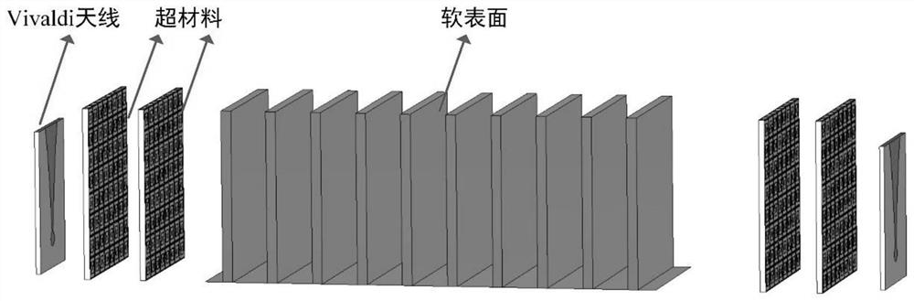
[0042] The purpose of the present invention is to propose an antenna decoupling method based on metamaterials and soft surfaces, which is embodied in that a metamaterial with negative equivalent electromagnetic parameters and a soft surface with electromagnetic wave blocking properties are used to load between two antennas to improve the decoupling between the antennas. isolation. The invention can be applied to the fields of phased array antennas, high-coupling MIMO arrays and the like.

[0043] The antenna decoupling method based on metamaterial and soft surface according to the embodim...


PUM


Abstract

The invention discloses an antenna decoupling structure and method based on a metamaterial and a soft surface. In the structure, an antenna structure is used for radiating or receiving space electromagnetic waves outwards; the top layer and the bottom layer of the metamaterial unit structure are the same split-ring resonator metal patterns, the middle layer is a medium FR4, and the structure enables the metamaterial unit structure to have negative medium parameter characteristics in a specific working frequency band and is used for inhibiting electromagnetic wave propagation between antenna structures; the band elimination characteristic is further improved by utilizing the blocking effect of the soft surface on electromagnetic waves; a metamaterial unit structure and a soft surface structure are combined and loaded between antenna structures, so that an isolation effect in a wide working frequency band is realized. According to the invention, the problem of antenna mutual coupling caused by space direct waves between antennas is solved, and the antenna can be applied to a phased-array antenna and a high-coupling MIMO (Multiple Input Multiple Output) array; the decoupling structure is simple in basic principle and clear in scheme, the designed decoupling structure is wide in working frequency band range and obvious in decoupling effect, and the decoupling structure has high application value.

Description

technical field [0001] The invention relates to the field of novel artificial electromagnetic materials, in particular to an antenna decoupling structure and method based on metamaterials and soft surfaces. Background technique [0002] Artificial electromagnetic materials refer to one-dimensional, two-dimensional or three-dimensional periodic artificial composite electromagnetic media / structures with extraordinary physical properties that conventional media in nature do not have. It has the advantages of processing and other advantages, and has a wide range of applications in the electromagnetic field. For example, artificial electromagnetic materials are used in antenna design to improve impedance matching characteristics, reduce antenna mutual coupling, increase antenna gain, and reduce antenna RCS. [0003] On the other hand, in modern communication, the requirements for the communication capacity and transmission rate of the antenna are getting higher and higher. Stro...

Claims


Application Information

Patent Timeline
Patent Type & Authority Applications(China)
IPC IPC(8): H01Q1/52H01Q15/00
CPCH01Q1/521H01Q15/0086H01Q15/0026
Inventor 曾宪亮吴为军陶理谭辉黄琛
Owner CHINA SHIP DEV & DESIGN CENT
Why Eureka
Try Eureka