
Adjustable direct-current stabilized power supply

A technology of DC regulated power supply and regulated power supply, which is applied in the direction of cabinet/cabinet/drawer parts, etc., can solve the problems of slow heat dissipation, cumbersome, troublesome cleaning, etc., to achieve the effect of easy protection and flexible connection

Inactive Publication Date: 2022-07-12
丁友良
View PDF1 Cites 0 Cited by
  • Summary
  • Abstract
  • Description
  • Claims
  • Application Information

AI Technical Summary

Problems solved by technology

[0002] When the existing regulated power supply is in use, the dust contained in the air will enter the inside of the regulated power supply from the heat dissipation holes on the regulated power supply, and accumulate in the inside of the regulated power supply for a long time, which will damage the regulated power supply. The operation of the power supply is affected and it is troublesome to clean it. At the same time, the regulated power supply itself can only dissipate heat through the cooling holes, resulting in slow heat dissipation during work, and the remaining heat remains inside the regulated power supply. Long-term use will cause circuit damage. Aging shortens the service life of the regulated power supply, and the regulated power supply lacks the necessary protective mechanism, and it will cause damage to the regulated power supply after falling vertically from a high place
[0003] In view of the above-mentioned problems, regarding the technical problems such as the inconvenient heat dissipation of the existing regulated power supply, after a large number of searches, a small adjustable DC regulated power supply with a patent number of CN202120803091.8 was found, including the regulated power supply body, The rear end of the stabilized power supply body is provided with a cooling device, the cooling device includes a connecting plate, cooling fan and installation strips, and the first protection mechanism is arranged on both sides of the stabilized voltage power supply body, the first protection mechanism includes a positioning screw, a mounting block, a protection Frame and dust-proof net, the bottom of the regulated power supply body is provided with a second protection mechanism; this patent is used to improve the heat dissipation performance of the regulated power supply by setting a cooling device, accelerate the heat dissipation speed of the regulated power supply, and set the first protection mechanism , to prevent dust from entering the inside of the regulated power supply from the heat dissipation holes and affecting the operation of the regulated power supply, and a second protection mechanism is set to play a buffer role to prevent the regulated power supply from falling vertically from a high place and causing direct damage , but the technical solution provided by this patent is to directly fix and connect the protective frame of the power supply through bolts, which is inconvenient to take and use the adjustable DC regulated power supply inside, which is relatively cumbersome

Method used


Image

  • Adjustable direct-current stabilized power supply
  • Adjustable direct-current stabilized power supply
  • Adjustable direct-current stabilized power supply

Examples


Embodiment 1

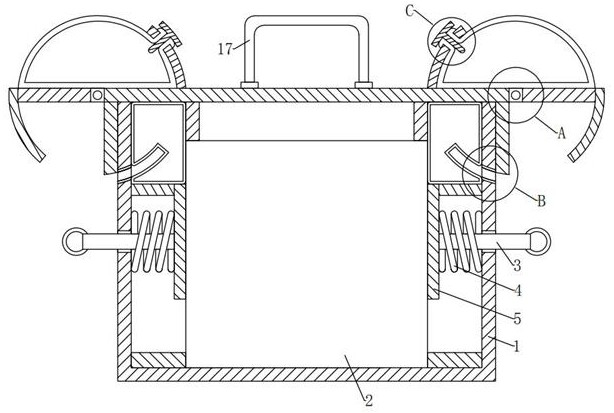
[0033] see Figure 1-2 and Figure 7 , In the embodiment of the present invention, a voltage-stabilized power supply based on an adjustable DC includes a box body 1, a bottom inner wall of the box body 1 is provided with a placement slot, and a regulated power supply body 2 is placed in the center of the placement slot, and the top of the box body 1 A protective component flexibly closed to the regulated power supply body 2 is movably installed, and the protective component includes: a connecting component flexibly connected to the box body 1 and an auxiliary component for auxiliary connection, and the connecting component and the auxiliary component are movably installed on the top of the box body 1;

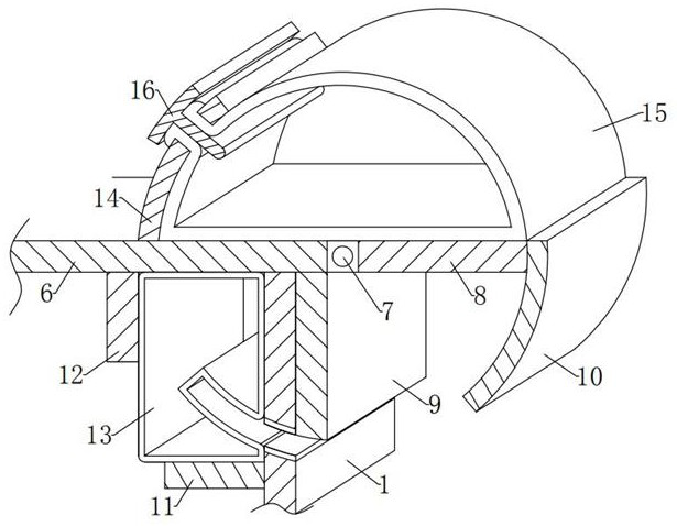
[0034]The connecting components include: a box cover 6, a rotating shaft 7, a rotating plate 8, a connecting plate 9 and a plug-in board 10, the box cover 6 is placed on the top of the box body 1, and the center of the left and right ends of the box cover 6 is rotatably install...

Embodiment 2

[0041] see Figure 1-4 and Figure 7 , with respect to Embodiment 1, the difference between the embodiment of the present invention is that the box cover 6 is in the shape of a horizontally long straight plate, and the left and right lengths of the box cover 6 are greater than the left and right lengths of the box body 1;

[0042] The box cover 6 here is for the convenience of closing the top side of the box body 1 and providing a carrier for the installation of the remaining connecting components and some auxiliary components.

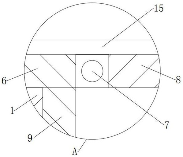
[0043] In the embodiment of the present invention, a circular groove is formed in the center of the tail of the left and right ends of the box cover 6, the front and rear ends of the left and right rotating shafts 7 are rotatably installed on the front and rear inner walls of the circular groove, and the rotating plate 8 is horizontal and right-arc. The shape of a short straight plate, the rotating plate 8 is magnetic, and the rotating plate 8 is in ...

Embodiment 3

[0051] see Figure 1-2 and Figure 5-7 , Compared with Embodiment 1, the difference between the embodiment of the present invention is that the support plate 11 is in the shape of a horizontal short straight plate, the top side outer surface of the support plate 11 is lower than the bottom end of the slot of the box body 1, the front and rear of the support plate 11 The outer surfaces of both sides are fixedly installed on the upper ends of the front and rear inner walls of the box body 1 , the limit plate 12 is in the shape of a vertical short straight plate up and down, and the bottom ends of the left and right limit plates 12 can touch the left and right tops of the regulated power supply body 2 ;

[0052] The supporting plate 11 and the limiting plate 12 here are for the convenience of supporting and limiting the two ends of the bottom and top of the lower airbag 13 respectively.

[0053] In the embodiment of the present invention, the lower airbag 13 has a fully enclosed...


PUM


Abstract

The invention provides an adjustable direct-current stabilized power supply which comprises a box body, a placement groove is formed in the inner wall of the bottom of the box body, a stabilized power supply body is placed in the center of the placement groove, and a protection assembly for flexibly sealing the stabilized power supply body is movably installed at the top end of the box body. The protection assembly comprises a connecting assembly flexibly connected with the box body and an auxiliary assembly for auxiliary connection, and the connecting assembly and the auxiliary assembly are movably installed at the top end of the box body. The connecting assembly comprises a box cover, rotating shafts, rotating plates, connecting plates and inserting plates, the box cover is placed at the top end of the box body, the rotating shafts are rotationally installed in the centers of the tails of the left and right ends of the box cover, the rotating plates are symmetrically and fixedly installed on the outer surfaces of one sides of the left and right rotating shafts in a surrounding mode, and the connecting plates are fixedly installed at the top ends of the left and right side walls of the box body. According to the adjustable direct-current stabilized power supply, the power supply is protected and closed without adopting bolts, so that the adjustable direct-current stabilized power supply can be conveniently taken, and the adjustable direct-current stabilized power supply is relatively simple and convenient and saves manpower.

Description

technical field [0001] The invention relates to the technical field of regulated power supplies, and more particularly, to an adjustable DC regulated power supply. Background technique [0002] When the existing regulated power supply is in use, the dust contained in the air will enter the inside of the regulated power supply from the heat dissipation holes on the regulated power supply, and accumulate inside the regulated power supply for a long time. At the same time, the regulated power supply itself can only dissipate heat through the heat dissipation holes, resulting in slow heat dissipation during operation, and the rest of the heat remains inside the regulated power supply. Long-term use will cause the circuit Aging shortens the service life of the regulated power supply, and the regulated power supply lacks the necessary protective mechanisms, which will cause damage to the regulated power supply after falling vertically from a high place. [0003] In view of the ab...

Claims


Application Information

Patent Timeline
Patent Type & Authority Applications(China)
IPC IPC(8): H05K5/02
CPCH05K5/0217
Inventor 丁友良刘西勇
Owner 丁友良
Learn More