High-precision worm and gear transmission mechanism

A technology of worm gear and transmission mechanism, which is applied in the direction of gear transmission, transmission, mechanical equipment, etc., can solve the problems of inconvenient worm synchronous drive function, inconvenient worm gear derivation work, and unfavorable intermittent regulation, etc., and achieves the phenomenon of intermittent regulation. , The effect of easy derivation work and smooth synchronous rotation

Pending Publication Date: 2022-07-22
江苏迈仕传动科技有限公司
View PDF2 Cites 0 Cited by
  • Summary
  • Abstract
  • Description
  • Claims
  • Application Information

AI Technical Summary

Problems solved by technology

[0006] It is not convenient to deduce the worm gear, which is not conducive to the intermittent regulation phenomenon. At the same time, it is not convenient to perform the synchronous drive function of the worm, which is not conducive to the overall stability. Therefore, a high-precision worm gear transmission mechanism is needed to solve the problem. questions raised in the above

Method used


Image

  • High-precision worm and gear transmission mechanism
  • High-precision worm and gear transmission mechanism
  • High-precision worm and gear transmission mechanism

Examples


Embodiment 1

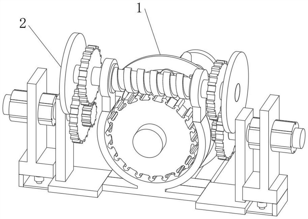
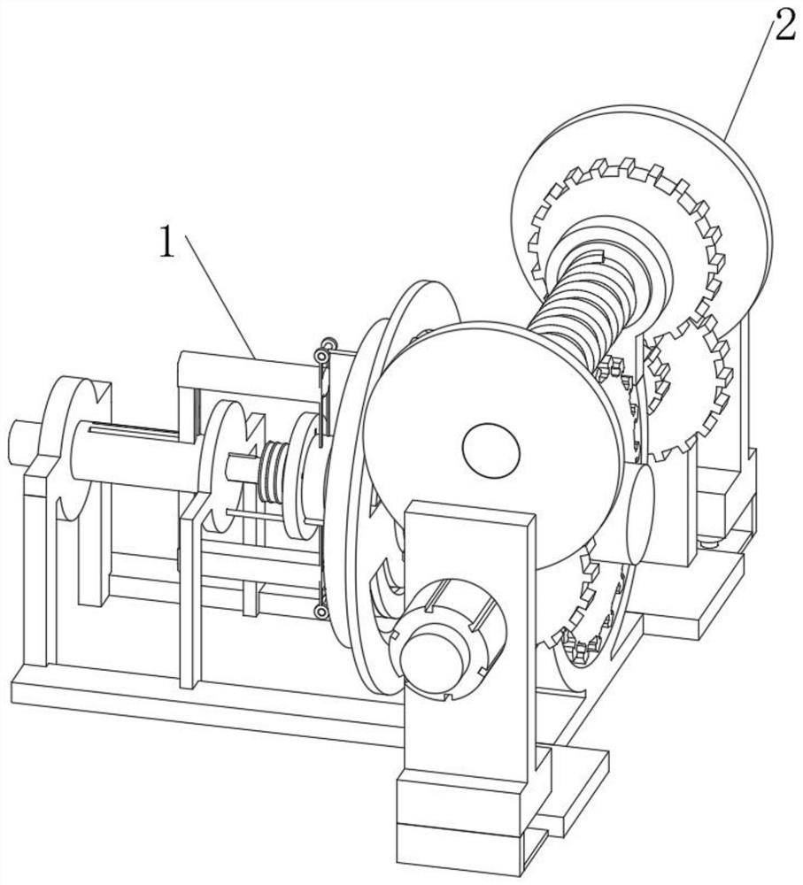
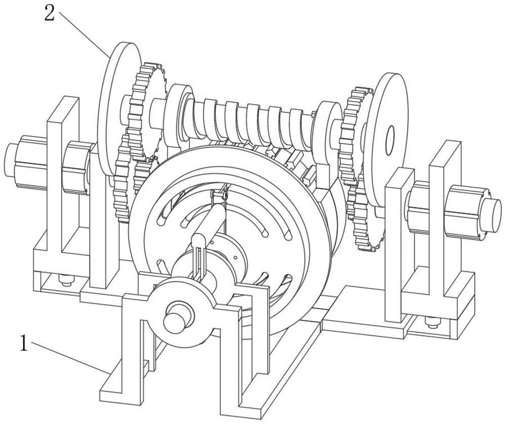
[0040] see figure 1 , figure 2 , image 3 , an embodiment provided by the present invention: a high-precision worm gear and worm drive mechanism, including a worm gear derivation connecting structure 1 and a worm connecting driving structure 2, and a worm connecting driving structure 2 is meshed and connected at the center front end of the worm gear derivation connecting structure 1 , through the combined connection of the worm gear derivation connection structure 1 and the worm connection drive structure 2, it is convenient for the integrated combination, which is helpful for the cooperative driving work;

[0041] see Figure 4 The worm gear derivation connection structure 1 includes a derivation transfer part 3 and a first support stand 4, the derivation and transfer part 3 is arranged at the central position of the worm gear derivation connection structure 1, and the rear end of the derivation transfer part 3 is in phase with the first support stand 4 The socket setting...

Embodiment 2

[0048] On the basis of Example 1, as Figure 8 As shown, the bottom side end of the worm connection drive structure 2 is communicated with a matching grooved pipe 29, the front end of the matching grooved pipe 29 is communicated with an oil feed pipe 28, and the front end of the oil feed pipe 28 is communicated with a communication pipe 27.

[0049] During the implementation of this embodiment, the user can communicate with the worm connection drive structure 2 by installing the communication pipe 27 , the oil supply pipe 28 and the matching groove pipe 29 , and the setting of the communication pipe 27 , the oil supply pipe 28 and the matching groove pipe 29 , and The bottom position of the communication pipe 27 is communicated with the outside world, which facilitates the oil supply work, realizes the internal lubrication work, and better reduces the internal resistance. For the purpose of lubrication, the communication pipe 27, the oil supply pipe 28, and the matching groove...


PUM


Abstract

The invention relates to the technical field of transmission equipment, and discloses a high-precision worm gear and worm transmission mechanism which comprises a worm gear pushing and guiding connecting structure and a worm connecting and driving structure, and the worm connecting and driving structure is connected to the front end of the center of the worm gear pushing and guiding connecting structure in an engaged mode. The worm wheel pushing and guiding connecting structure comprises a pushing and guiding transferring part and a first supporting rack, the pushing and guiding transferring part is arranged at the center position of the worm wheel pushing and guiding connecting structure, and the rear end of the pushing and guiding transferring part is connected with the first supporting rack in a sleeved mode. The bottom end of the first supporting rack is fixedly connected with a bottom supporting plate, and the center position of the bottom supporting plate is fixedly connected with the second supporting rack. Through the arrangement of the worm gear pushing and guiding connecting structure and the worm connecting and driving structure, high-precision worm gear and worm transmission work is achieved, and the purpose of better driving treatment is achieved.

Description

technical field [0001] The invention relates to the technical field of transmission equipment, in particular to a high-precision worm gear transmission mechanism. Background technique [0002] The worm gear and worm can obtain a large transmission ratio, which is more compact than the staggered-axis helical gear mechanism. The meshing tooth surfaces of the two wheels are in line contact, and its bearing capacity is much higher than that of the staggered-axis helical gear mechanism. The worm drive is equivalent to a screw drive. Meshing transmission, so the transmission is stable, the noise is small, and it has self-locking. When the lead angle of the worm is less than the equivalent friction angle between the meshing gear teeth, the mechanism has self-locking, which can realize reverse self-locking, that is, only the worm can be locked. It drives the worm wheel, but the worm cannot be driven by the worm wheel. For example, the self-locking worm mechanism used in hoisting mac...

Claims


Application Information

Patent Timeline
Patent Type & Authority Applications(China)
IPC IPC(8): F16H1/22F16H57/04
CPCF16H1/222F16H57/042F16H57/0498F16H57/0456
Inventor 颜辉滨朱雪娟张美勤赵永
Owner 江苏迈仕传动科技有限公司
Why Eureka
Try Eureka