Supercharge Your Innovation With Domain-Expert AI Agents!

Vibrator holder

A technology of clamping device and vibrator, which is applied in the direction of electromechanical device, signal device, connection with grounding device, etc.

Inactive Publication Date: 2004-05-05
PANASONIC CORP
View PDF2 Cites 0 Cited by
  • Summary
  • Abstract
  • Description
  • Claims
  • Application Information

AI Technical Summary

Problems solved by technology

Therefore, produced the 5th problem, namely, the problem that a vibrating motor 72 encounters

Method used


Image

  • Vibrator holder
  • Vibrator holder
  • Vibrator holder

Examples


Embodiment Construction

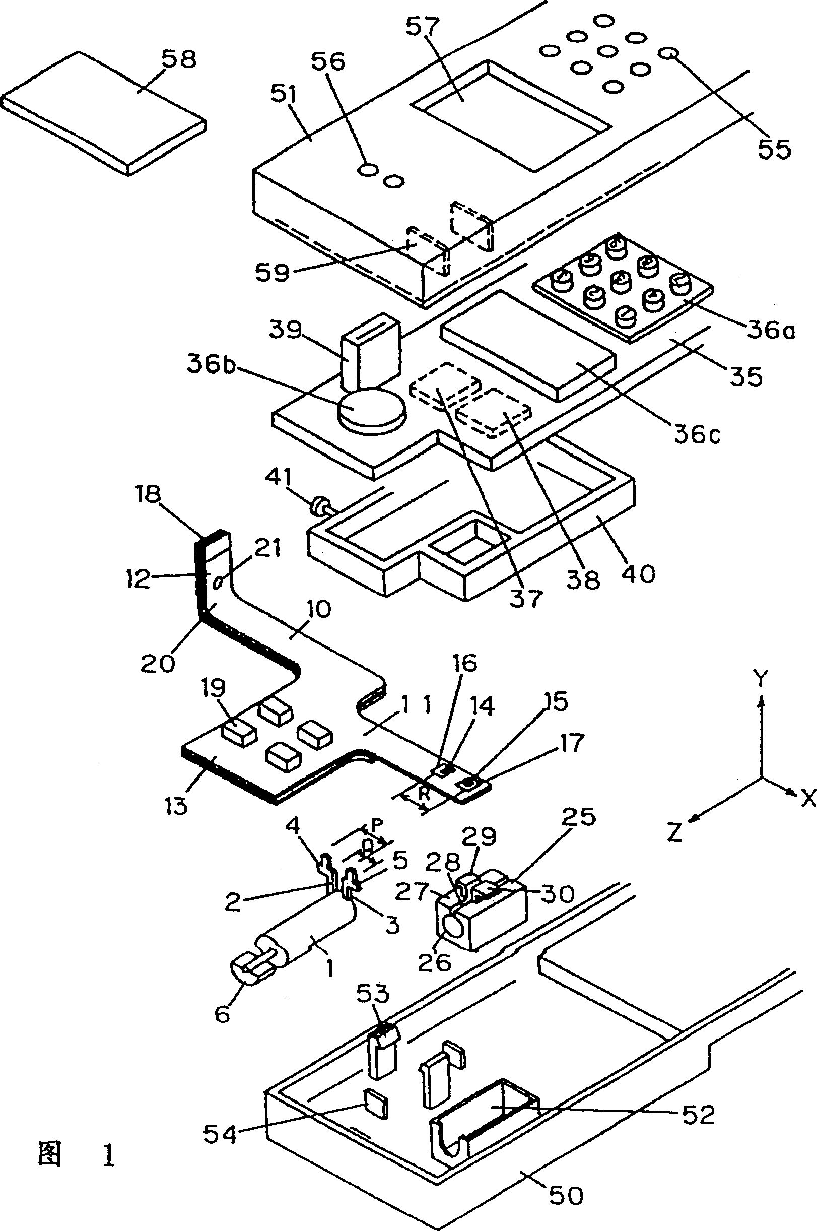
[0037] Referring now to the drawings, a mobile phone mounted with a vibrator holding device according to a first embodiment of the present invention will be described. Fig. 1 is an exploded perspective view of the schematic structure of the mobile phone on which the vibrator holding device according to the present invention is mounted.

[0038] See Fig. 1, this vibrator clamping device has: a flexible printed circuit board 10; Vibration motor 1, it is connected with flexible printed circuit board 10, can vibrate; A motor pad 25, plays the effect of elastic clamping part, elastic Clamp the vibration motor 1; and a frame 52, which acts as a clamp, fixes the motor pad 25 in the housing 50 of the device, which will be described later.

[0039] The vibration motor 1 is a DC coreless motor having a cylindrical shape, which includes: a metal case (not shown); a rotating shaft (not shown) in the metal case of the motor; a bearing (not shown) supporting the rotating shaft ); a cup-sha...


PUM


Abstract

Disclosed is a vibrator holding device, which comprises a vibration generator device (101) used for generating vibrations; a first elastic cushion (125) used for holding said vibration generator device, wherein a part (146) of said vibration generator device is exposed from said first elastic cushion; and a second cushion (130) comprising a conducting part (143), wherein the second cushion holds the first cushion and the part exposed (146) of the vibration generator device contacts and is electrically connected to the conducting part (143). The contacting direction of the part exposed (146) of the vibration generator device and the conducting part (143) is different from the vibration generating direction of the vibration generator device.

Description

[0001] This application is a divisional application of the invention patent application filed on August 28, 1997 by Matsushita Electric Industrial Co., Ltd. with the name "vibrator clamping device" and application number 97117755.4. technical field [0002] The present invention relates to a vibrator holding device incorporated in a pager, mobile phone, etc., the vibrator silently notifies the user that the pager, mobile phone, etc. has received a call. Background technique [0003] Here, as described below, the above-mentioned vibrator holding device is provided in, for example, a mobile phone. [0004] The vibrator holding device of the above-mentioned type is constructed such that a flexible printed circuit board is provided in a casing of a mobile phone. Also, a bracket made of a thin metal plate holding the vibrator motor is mounted on the flexible printed circuit board, and leads of the held motor are connected to the flexible printed circuit board. [0005] When a fl...

Claims


Application Information

Patent Timeline
IPC IPC(8): G08B6/00H02K5/22H02K5/24H02K7/06H02K23/58H05K1/18H05K3/30
CPCH02K7/061H02K23/58H02K11/0089H02K2211/03H05K3/301H02K5/24H05K1/189H02K5/225G08B6/00H02K11/40
Inventor 佐藤则喜小西一弘
Owner PANASONIC CORP
Features
  • R&D
  • Intellectual Property
  • Life Sciences
  • Materials
  • Tech Scout
  • Unparalleled Data Quality
  • Higher Quality Content
  • 60% Fewer Hallucinations
Learn More