Supercharge Your Innovation With Domain-Expert AI Agents!

Multifocal ophthalmic lens

A lens and focal power technology, applied in the field of multi-focal eye lenses, can solve problems such as discomfort and achieve good observation comfort

Inactive Publication Date: 2004-08-25
ESSILOR INT CIE GEN DOPTIQUE
View PDF3 Cites 0 Cited by
  • Summary
  • Abstract
  • Description
  • Claims
  • Application Information

AI Technical Summary

Problems solved by technology

Wearers of multifocal lenses actually often experience discomfort during dynamic viewing

Method used


Image

  • Multifocal ophthalmic lens
  • Multifocal ophthalmic lens
  • Multifocal ophthalmic lens

Examples


Embodiment Construction

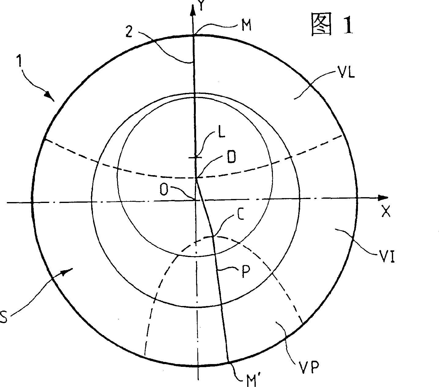
[0041] In the following, an orthogonal coordinate system will be used, where the X-axis corresponds to the horizontal axis of the lens and the Y-axis corresponds to the vertical axis; the center O of the reference frame is the geometric center of the lens.

[0042] Fig. 1 is a schematic front view of a known progressive eye lens showing its various elements.

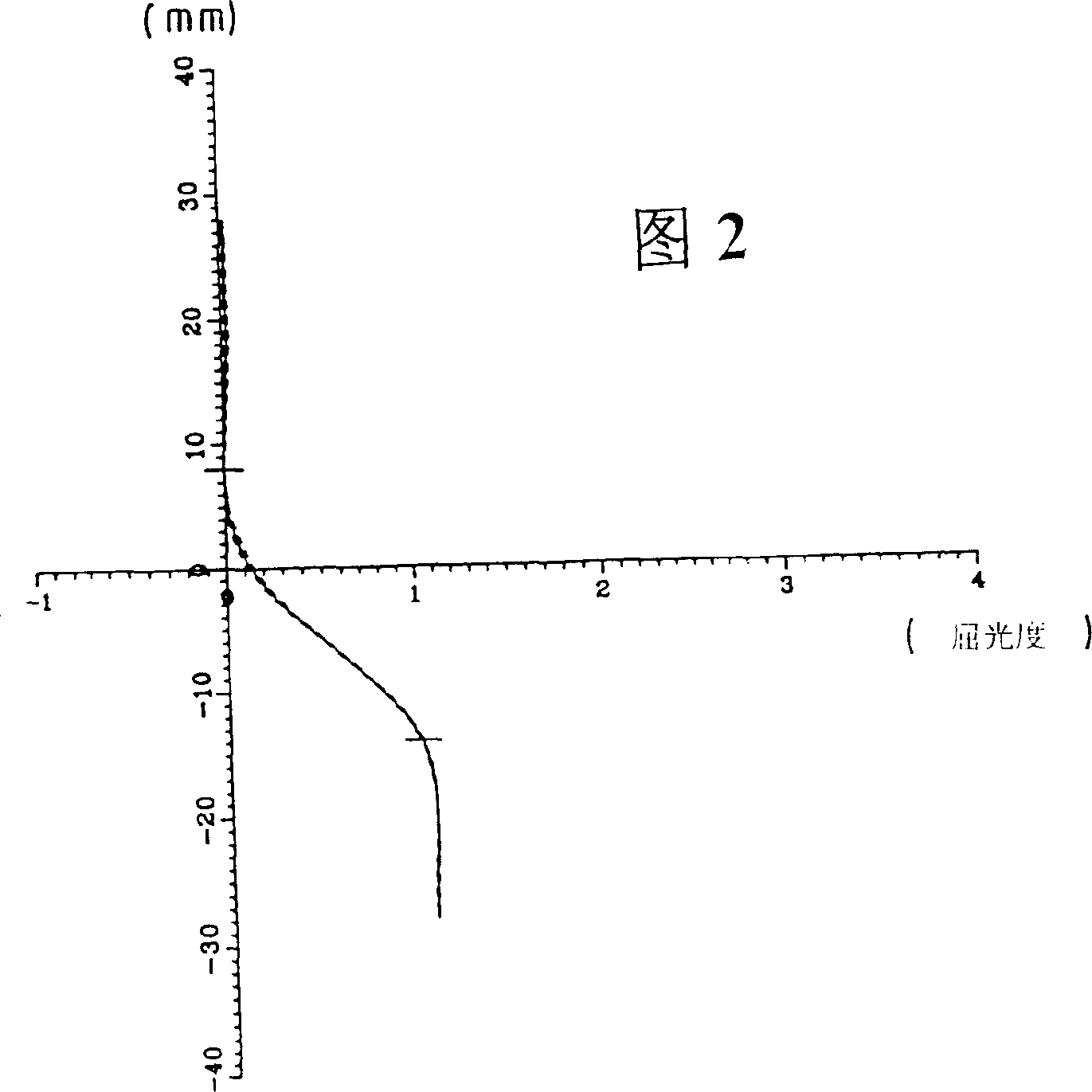
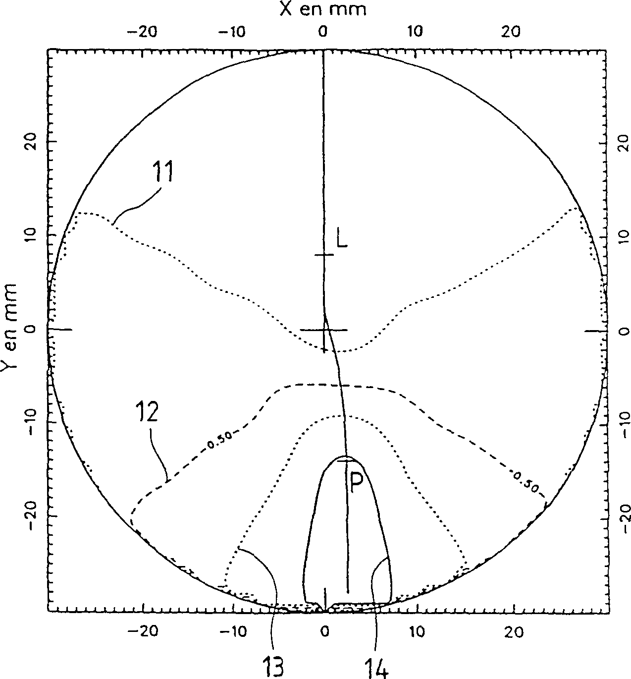
[0043] Figure 2 to Figure 4 The optical properties of a lens according to the invention having a diameter of about 60 mm are shown. In FIGS. 2 to 4 , lenses having a power addition of one diopter are described.

[0044] Figures 5 to 10 show similar views for a lens with a power addition of 2 or 3 diopters.

[0045] Referring to Fig. 1, various elements of a multifocal eye lens will be described. Such a lens typically has an aspheric surface as shown in Figure 1 and a second surface which may be aspheric or toroidal.

[0046] For each point on the aspheric surface, an average steradian D is determined by the followin...


PUM


Abstract

A multifocal ophthalmic lens comprising a far vision region, a near vision region and an intermediate vision region is provided having a high near vision region and a wide vision field in the near vision region, the intermediate vision region and in the far vision region. Progression is gentle although the distance between a mounting center on the lens and the point where power addition is 85% higher than power addition at a far vision control point is less than 16 mm, while simultaneously maximum cylinder inside a 20 mm radius circle centered on a geometrical center of the lens is kept at a low value.

Description

technical field [0001] The present invention relates to a multifocal eye lens having an aspheric surface having a mean sphere and a cylinder at each point on the aspheric surface. Background technique [0002] Such lenses are already well known; among multifocal lenses, a distinction can be made between lenses suitable for all-distance vision, known as progressive lenses, and lenses dedicated more specifically for near-distance and intermediate-distance vision. [0003] The progressive multi-focal eye lens includes a distance viewing zone, a near viewing zone, a middle distance viewing zone and a gradual main meridian passing through the three viewing zones. French patent application 2,699,294, incorporated herein by reference, describes in its introduction the elements of the progressive multifocal eye lens (gradient main meridian, distance vision zone, near distance vision zone, etc.) work done in comfort. [0004] In order to better meet the viewing needs of hyperopic p...

Claims


Application Information

Patent Timeline
IPC IPC(8): G02C7/06G02C7/02
CPCG02C2202/08G02C7/061G02C7/065
Inventor 吉勒斯·勒索克洛德·佩德罗诺克莱雷·罗西耶
Owner ESSILOR INT CIE GEN DOPTIQUE
Features
  • R&D
  • Intellectual Property
  • Life Sciences
  • Materials
  • Tech Scout
  • Unparalleled Data Quality
  • Higher Quality Content
  • 60% Fewer Hallucinations
Learn More