
Luminescence display panel using discharge gas

A discharge gas and display panel technology, applied to AC plasma display panels, discharge tubes, electrical components, etc., can solve problems such as deterioration of color contrast

Inactive Publication Date: 2004-08-25
PANASONIC CORP
View PDF0 Cites 0 Cited by
  • Summary
  • Abstract
  • Description
  • Claims
  • Application Information

AI Technical Summary

Problems solved by technology

This in turn worsens the color contrast of each color

Method used


Image

  • Luminescence display panel using discharge gas
  • Luminescence display panel using discharge gas
  • Luminescence display panel using discharge gas

Examples


Embodiment Construction

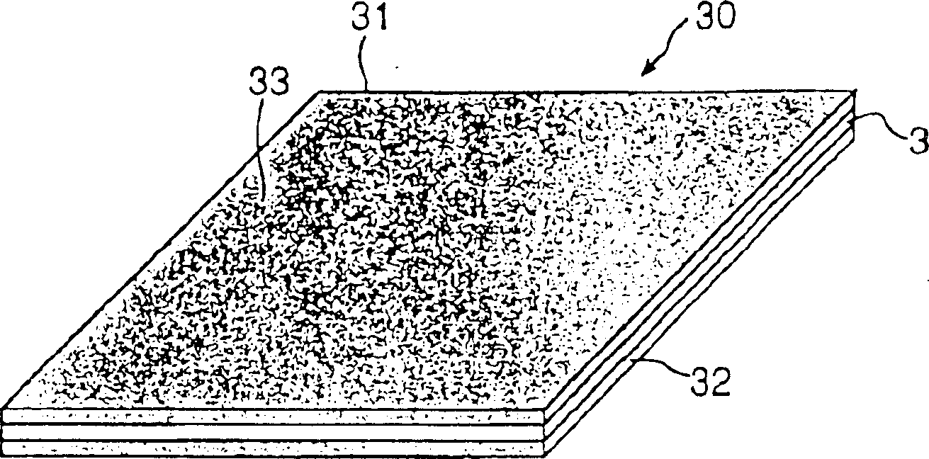
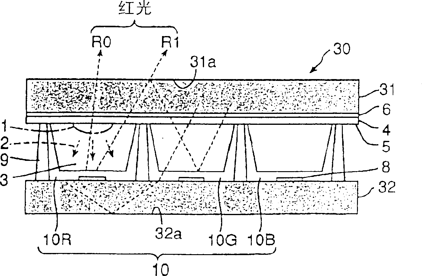
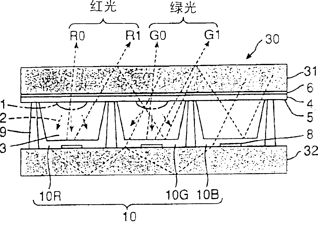
[0024] refer to figure 1 , shows an AC (alternating current) plasma display panel, generally indicated by reference numeral 30, which is an embodiment of the present invention using a discharge gas fluorescent display panel. The AC plasma display panel 30, illustrated with an upwardly pointing display surface 33, comprises a front panel 31 and a rear panel 32, both of dark colour. The plates 31 and 32 are spaced apart from each other to form a discharge chamber 3 therebetween. The AC plasma display panel 30 is similar to the above-mentioned conventional AC display panel 20 except for the surface and the rear panel, and has a dark color. Therefore, in the following description, the same reference numerals are used for the same elements, and their detailed descriptions are omitted. Also, the physical structures shown are similar to those described above, except for the darkness of the panels, so they will not be described in the following description.

[0025] figure 2 and...


PUM


Abstract

A gas discharge display panel has surface and rear plates. The plates are spaced apart from each other, forming a chamber in which a discharge gas is contained. Also, both surface and rear plates are dark in color. Preferably, both surface and rear plates have a darkness of about 20% or more or a transparency of about 80% or less. This decreases halation of light, preventing the mixing of color. Also, the gas discharge display panel provides a high contrast and clear images to the viewers.

Description

technical field [0001] The present invention relates to light emitting display panels using discharge gas for use in television sets and computer systems. Background technique [0002] Image 6 A conventional light-emitting display panel using a discharge gas is shown, indicated generally at 20, which is preferably used in a plasma display system. The display panel 20 comprising a transparent front panel 21 and a rear panel 22 spaced apart from each other is drawn such that a surface 23 of the front panel remote from the rear panel 22 points upwards. [0003] also, Figure 7 An enlarged partial schematic view of an AC plasma display panel is shown, which is an example of such an illuminated display panel. As shown, the display panel 20 includes discharge cells 3 between a surface 23 and a rear panel 22 . The other surface of the front panel 21 opposite to the backplane electrode 22 supports a plurality of pairs of elongated scan electrodes 6 and sustain electrodes 7 exten...

Claims


Application Information

Patent Timeline
IPC IPC(8): H01J11/12H01J11/24H01J11/26H01J11/34H01J11/36H01J11/42H01J11/44H01J17/16
CPCH01J2211/34H01J11/44H01J2211/444H01J11/12H01J11/34
Inventor 平尾和则青砥宏治田原宣仁
Owner PANASONIC CORP
Learn More