Check patentability & draft patents in minutes with Patsnap Eureka AI!

An aerosol valve

A spray valve and valve stem technology, applied in the direction of injection device, liquid injection device, engine sealing, etc., can solve the problems of non-utilization, leakage of hardness sealing ring characteristics, etc.

Inactive Publication Date: 2005-01-26
PRECISION VALVE CORP
View PDF1 Cites 0 Cited by
  • Summary
  • Abstract
  • Description
  • Claims
  • Application Information

AI Technical Summary

Problems solved by technology

[0008] It is now recognized that the characteristics of single durometer seals are prone to leakage problems
For a single hardness seal ring, there is a compromise in the selection of a single hardness seal ring to meet the needs of different hardness in the above two sealing areas, resulting in no utilization of the maximum yield in each area. Sealing ring hardness for sealing performance

Method used


Image

  • An aerosol valve
  • An aerosol valve
  • An aerosol valve

Examples


Embodiment Construction

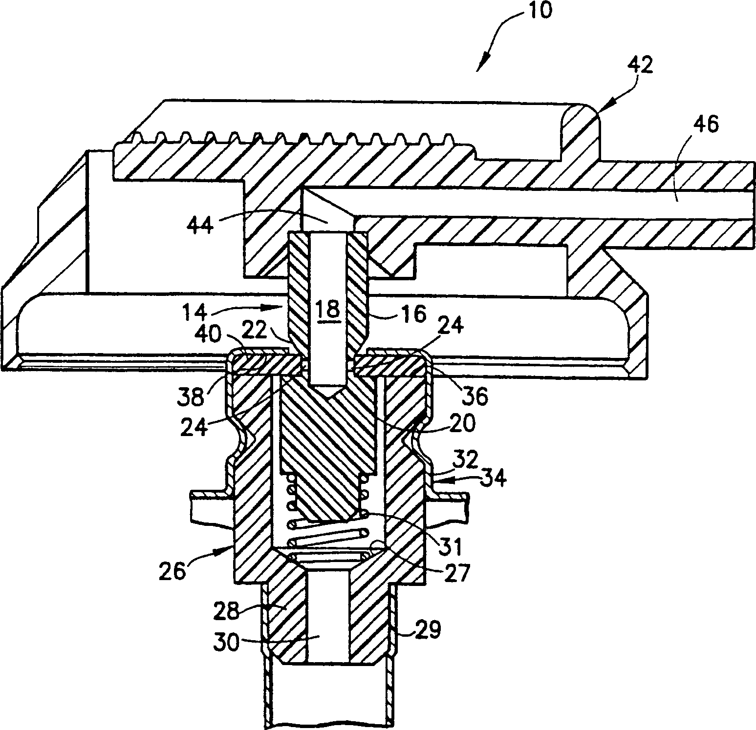
[0015] Figure 1 shows a spray valve assembly, generally indicated by the numeral 10. More specifically, the valve assembly includes: a valve stem / stem body indicated at numeral 14 having an upper valve stem portion 16 through which conduit 18 passes; a valve Stem portion 20 and an annular groove portion 22 in the middle portion between the upper stem portion 16 and the valve stem body portion 20; the groove portion has a hole 24 passing through the wall of the groove portion, and the groove portion passes through the hole and the tube. Road 18 is connected. Valve housing 26 surrounds valve stem body 20, said valve housing has an extended nipple 28 through which conduit 30 passes, nipple 28 designed to accept cannula 29 (shown in FIG. part). The valve housing 26 is captured within a base portion 34 of a mounting cup 34 (partially shown). An annular seal 40 is disposed on top of the upper wall 36 of the valve housing 26 and at the underside 38 of the seat portion 32 to seal a...


PUM


Abstract

An improved valve stem gasket comprising a flat-shaped gasket with a central aperture wherein the durometer of the gasket varies from a relatively low hardness value in the inner portion of the gasket extending radially outward from the central aperture to a relatively higher hardness value at the radially outer portion of the gasket whereat the gasket will be contacted by the upper wall portion of the valve housing. In a preferred form of the gasket, the variation in durometer value will be gradually varied from the inner portion of the gasket to the radially outer portion of the gasket.

Description

technical field [0001] The invention relates to a spray valve, in particular to a sealing ring for sealing a valve stem hole of the spray valve. Background technique [0002] Spray containers are widely used to package a variety of fluid materials, including both liquid products and powdered particulate products. Typically, the product and propellant are enclosed in a container above atmospheric pressure and the product is delivered by manually opening a dispensing valve to create pressure in the container so that the product is discharged from the container through the valve and tubing connected to the discharge orifice out. [0003] The dispensing valve, which clips onto a mounting cup, has a sealing ring and typically fits in the top opening of the container defined by a feature commonly referred to as the "bead" of the container opening. The mounting cup includes a central seat portion for holding the dispensing valve and a side portion extendi...

Claims


Application Information

Patent Timeline
Patent Type & Authority Patents(China)
IPC IPC(8): B65D83/44B05B9/04B65D83/14F16J15/10F16J15/16
CPCF16J15/104B65D83/38Y10S277/944F16J15/14
Inventor 汉斯·哈夫纳
Owner PRECISION VALVE CORP
Features
  • R&D
  • Intellectual Property
  • Life Sciences
  • Materials
  • Tech Scout
  • Unparalleled Data Quality
  • Higher Quality Content
  • 60% Fewer Hallucinations
Learn More