Magnetron

A magnetron and pole piece technology, applied in the field of magnetrons, can solve problems such as damage to high-voltage parts, and achieve the effects of preventing discharge and inhibiting the reduction of insulation resistance

Inactive Publication Date: 2005-02-02
SANYO ELECTRIC CO LTD
View PDF1 Cites 0 Cited by
  • Summary
  • Abstract
  • Description
  • Claims
  • Application Information

AI Technical Summary

Problems solved by technology

[0004] Therefore, in a microwave oven using a magnetic flux leakage transformer, if the power is turned on without preheating the filament, a 8-10kV no-load voltage is applied to the magnetron at the initial stage when electrons are not released, and the cylindrical metal container If the insulation resistance of the joint surface and the cathode lead wire is reduced, discharge occurs between the joint surface of the cylindrical metal container and the cathode lead wire through the bottom surface of the insulator sleeve, causing an overvoltage wave and causing damage to high-voltage parts.

Method used


Image

  • Magnetron
  • Magnetron
  • Magnetron

Examples


Embodiment 1

[0019] Embodiment 1 of the present invention will be described in detail based on the drawings.

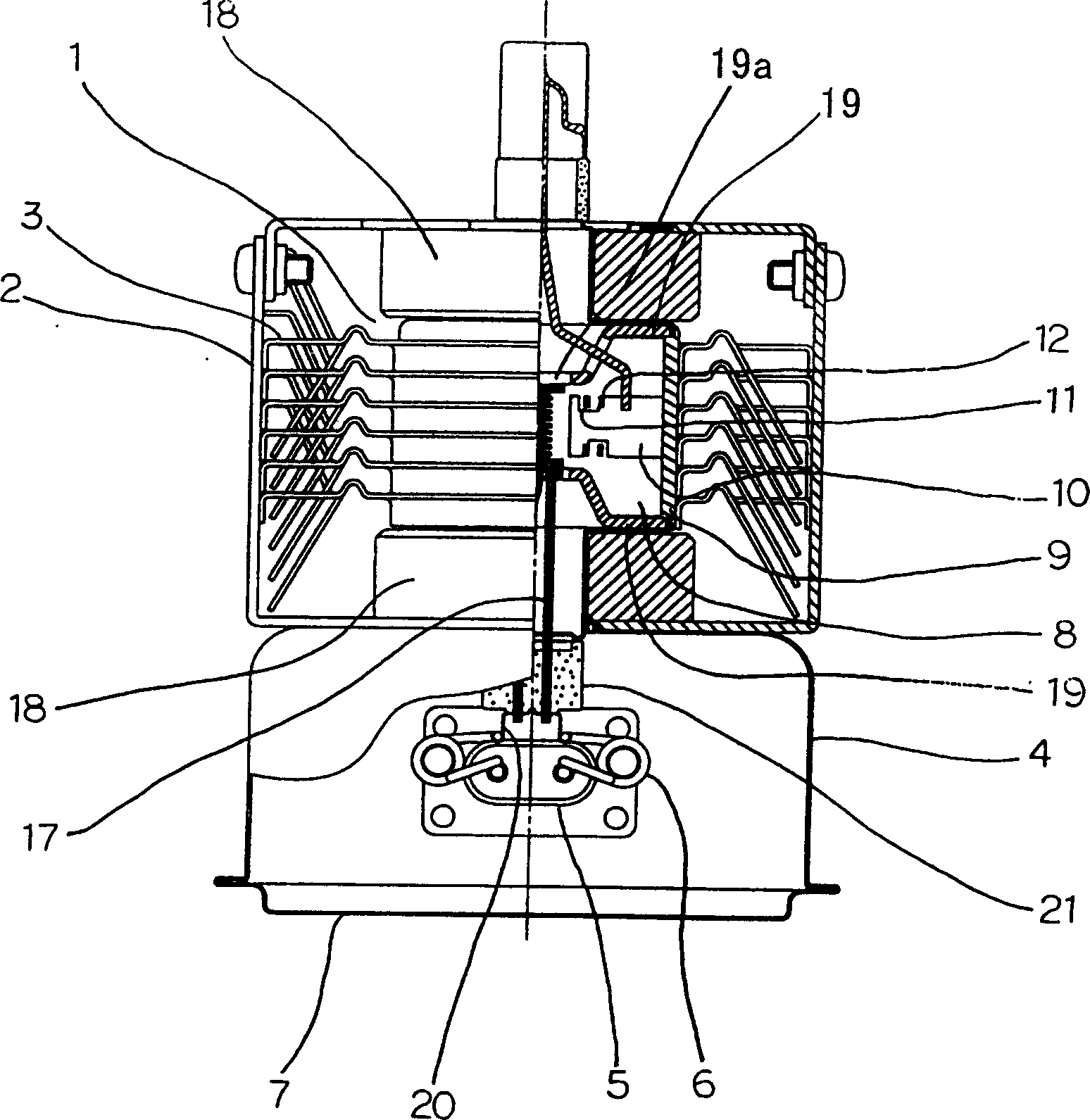
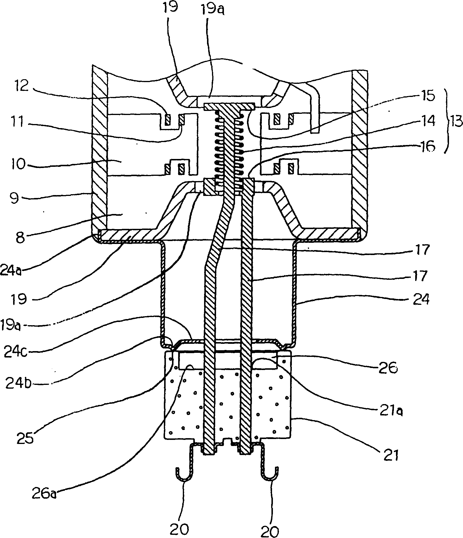
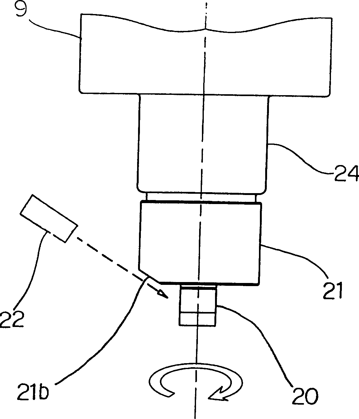
[0020] figure 1 It is a longitudinal sectional view showing the main part of the magnetron of the first embodiment of the present invention, figure 2 Is a longitudinal section of the same main part, image 3 Is a cross-sectional view of the same main part, Figure 4 Is the top surface view of the same insulator sleeve, Figure 5 It is a diagram showing another embodiment of the insulator sleeve.

[0021] 1 is the main body of the magnetron of the vacuum diode covered by the frame 2 and the heat sink 3.

[0022] 4 is a case in which the capacitor 5 and the choke coil 6 for noise suppression are installed inside, and the cover 7 is attached to the opening of the case 4 so that the noise does not leak to the outside.

[0023] 8 is the anode of the magnetron. The anode 8 is made of oxygen-free copper. The anode cylinder 9 that forms a part of the vacuum wall of the main body 1 is used....

Embodiment 2

[0037] Hereinafter, Embodiment 2 of the present invention will be described based on the drawings. The same numbers are attached to the same structures in the first embodiment described above, and the descriptions are omitted.

[0038] Figure 6 It is a longitudinal sectional view of the main part of Example 2 of the present invention.

[0039] 27 is a cylindrical metal container in which one end 27a is joined to the anode 8 and the other end 27b is brazed and hermetically joined to the joining surface 25 formed around the insulator sleeve 21.

[0040] 27c is a bent portion formed in the cylindrical metal container 27 and bent from the other end opening 27b to the bottom surface 26a of the recess 26, and the bent portion 27c is formed to cover the entire bottom surface 26a of the recess 26. With this structure, even if metal objects such as thorium and tungsten are evaporated from the surface of the filament 14, because the bent portion 27c covers the entire wall surface 26b of th...


PUM


Abstract

A cathode 13 with a filament 14 arranged at a center axis part of an anode 18 is supported by a pair of cathode leads 17, a pair of magnetic pole pieces 19 with a through-hole 19a formed at around the center are arranged at both ends of the anode 8, an opening 24b at one end of a cylindrical metal container 24 is joined airtightly with a junction face formed at a stem insulating body 21, a circular brim part 24c set in extension at the side of the cathode leads 17 is formed at the opening 24b, and a bottom face 26a of the stem insulating body 21 is to be covered with the brim part 24c. To surely prevent discharge generated between a junction part of a stem insulating body with a cylindrical metal container and cathode leads.

Description

Technical field [0001] The invention relates to a microwave generating magnetron installed in a microwave oven. Background technique [0002] The cathode part of the conventional magnetron for microwave oven is described in Japanese Patent Publication No. 7-62979 (H01J 23 / 14, H01J 9 / 24, H01J 23 / 12), and both ends of a filament made of thorium tungsten They are respectively fixed to a pair of end boxes, and a cathode lead made of molybdenum (Mo) is fixed in this end box. These cathode leads extend to the outside through the through hole of the insulator sleeve, and a cylindrical metal container with one end of the anode fixed on the metal sprayed surface of the insulator sleeve is brazed with solder. A pair of magnetic pole pieces with a through hole in the center are arranged on both ends of the anode to guide the magnetic force of the magnet not shown in the figure to the vicinity of the filament. [0003] In a magnetron with this structure, the cylindrical metal container that ...

Claims


Application Information

Patent Timeline
Patent Type & Authority Patents(China)
IPC IPC(8): H01J23/14H01J23/04H01J23/15H01J25/50
CPCH01J9/323H01J23/15H01J29/865
Inventor 村尾则行长谷川节雄中井聪冈田则幸三木一树
Owner SANYO ELECTRIC CO LTD
Why Eureka
Try Eureka