
Power supply device

A power supply device and battery technology, which is applied in the direction of batteries, circuits, electric vehicles, etc., can solve the problems of shortened creepage distance on the bottom surface of the battery unit, and cannot effectively prevent leakage, etc., achieve excellent insulation characteristics, improve the reduction and increase of insulation characteristics The effect of creepage distance

Active Publication Date: 2019-04-16
SANYO ELECTRIC CO LTD
View PDF6 Cites 5 Cited by
  • Summary
  • Abstract
  • Description
  • Claims
  • Application Information

AI Technical Summary

Problems solved by technology

However, on the bottom surface of the battery cells 91 of this battery stack, joints are formed between the insulating ribs 93 of the separators arranged on both sides, and dew condensation water enters the joints. The creepage distance is shortened and cannot effectively prevent leakage

Method used


Image

  • Power supply device
  • Power supply device
  • Power supply device

Examples


Embodiment Construction

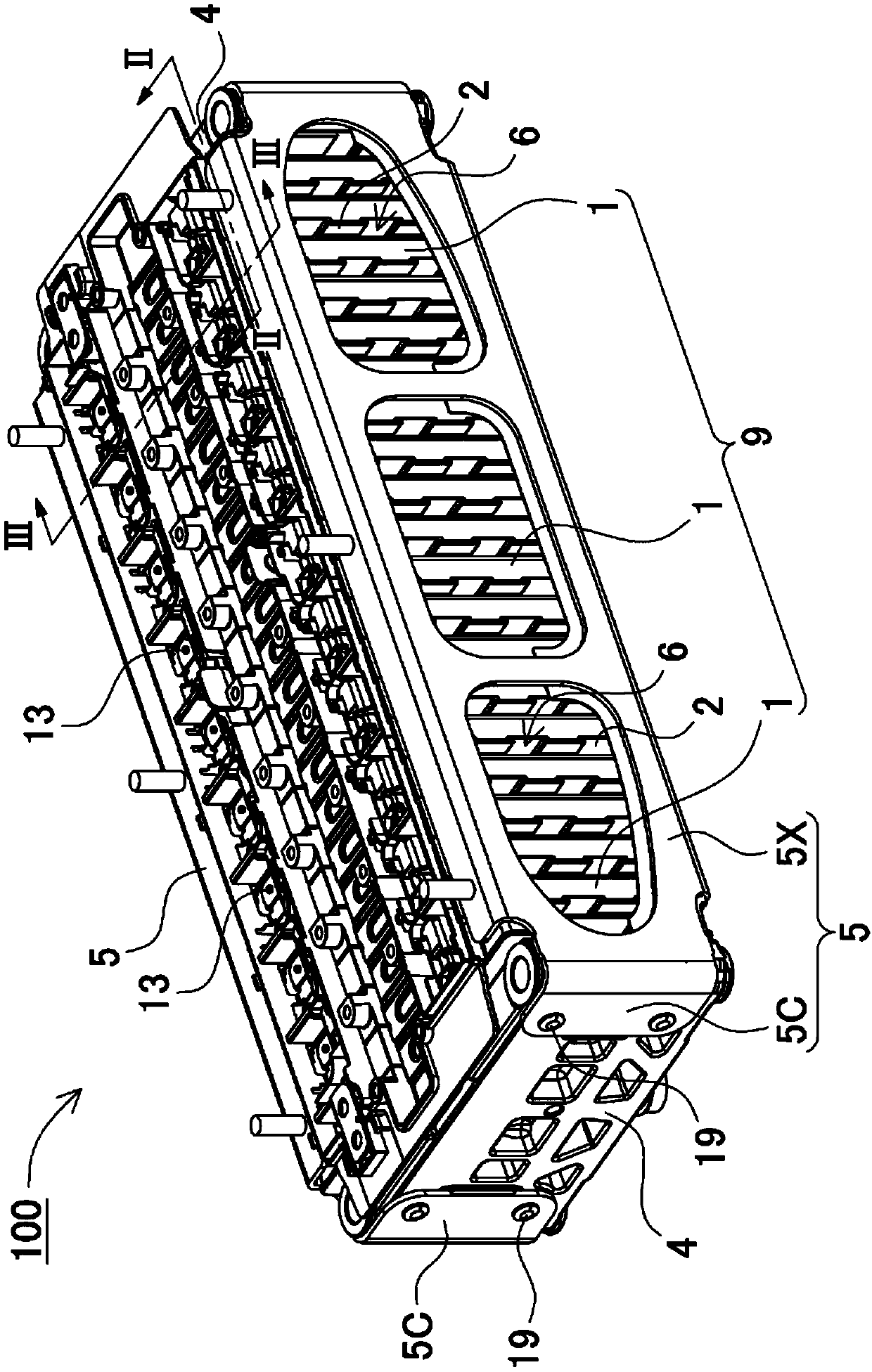
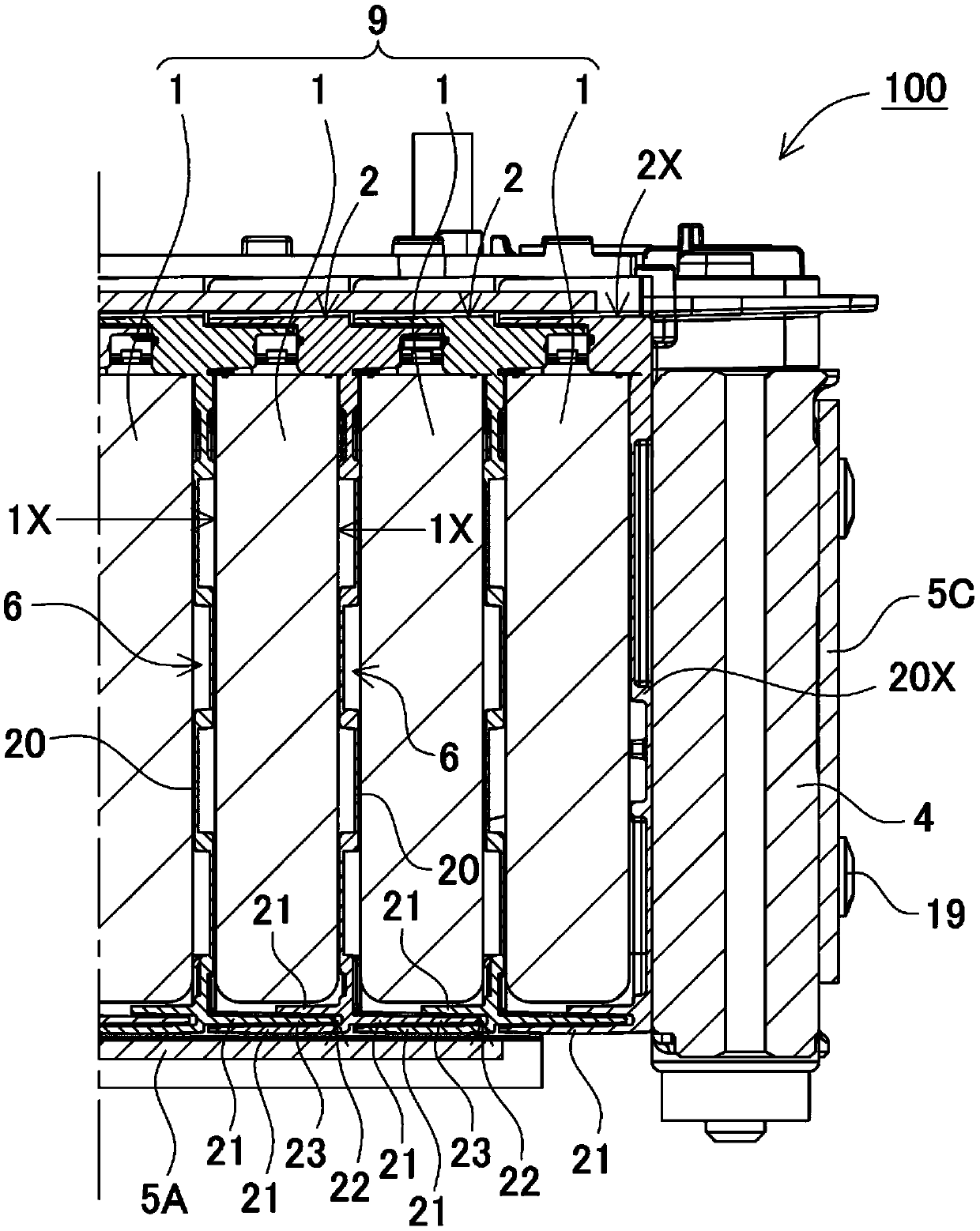
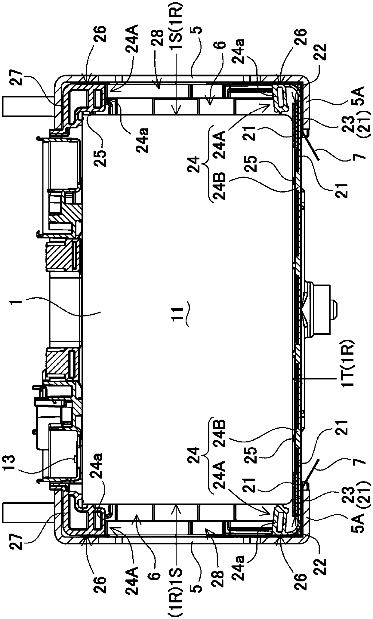
[0042] exist Figure 1 ~ Figure 3 A power supply device according to an embodiment of the present invention is shown in . The power supply device 100 in the above-mentioned figure includes: a plurality of battery cells 1 with a square shape; a separator 2 sandwiched between a plurality of battery cells 1 to insulate the battery cells 1; a battery stack 9, which A plurality of battery cells 1 insulated by separators 2 are stacked with main surfaces 1X facing each other; end plates 4 are arranged at both ends of the battery stack 9; end plate 4.

[0043] (battery unit 1)

[0044] The battery cell 1 is a lithium-ion secondary battery whose main surface 1X, which is a wide surface, has a quadrangular shape and is thinner than the width of the main surface 1X. However, in the power supply device of the present invention, the battery unit 1 is not specified as a lithium ion secondary battery. This is because all secondary batteries currently used and developed in the future, suc...


PUM


Abstract

The purpose of the present invention is to effectively prevent, using a very simple structure, power leakage caused by dew condensation water or the like by increasing a creeping distance of a batterycell bottom surface. Provided is a power supply device that comprises: a plurality of battery cells (1) having a square outer shape; separators that are arranged between the battery cells (1); a pairof end plates that are disposed at the two ends of a battery multilayer body that is formed by stacking a plurality of the separators and the battery cells (1) on top of one another; and a binding bar that binds the pair of end plates to each other. The separators are provided such that insulating rib parts (21) thereof, which are disposed on bottom surfaces of the battery cells (1) stacked at both sides, are provided so as to protrude toward both surfaces, and the insulating rib parts (21) of the separators, which are stacked on both surfaces of the battery cells (1), are stacked on the bottom surfaces of the battery cells (1). An insertion rib (23), which is provided on one stacked insulating rib part (21), is inserted into an insertion groove (22), which is provided in another stackedinsulating rib part (21), the insulating rib parts (21) are stacked one top of the other, and the insulating rib parts (21), which have a curved U shape creeping distance, are disposed on the bottom surfaces of the battery cells (1).

Description

technical field [0001] The invention relates to a power supply device in which a plurality of battery cells are laminated through separators. Background technique [0002] A power supply device including a plurality of battery cells is used in applications such as a power supply for driving a vehicle. Such a power supply unit includes a plurality of battery cells, a plurality of separators, a pair of tie bars, and a pair of end plates. Each separator is arranged between adjacent battery cells to arrange the adjacent battery cells in an insulated state. A battery stack is formed by alternately stacking a plurality of battery cells and a plurality of separators. End plates are arranged on both end surfaces of the battery stack in the stacking direction of the battery cells. The battery cells are fixed in a stacked state by connecting them with end plates disposed on both end surfaces. Since the positive and negative electrode plates and the electrolytic solution are sealed...

Claims


Application Information

Patent Timeline
Patent Type & Authority Applications(China)
IPC IPC(8): H01M2/10H01M2/02H01M10/613H01M10/625H01M10/627H01M10/647H01M10/6557H01M10/6563H01M50/103H01M50/209
CPCH01M10/625H01M10/6563H01M10/647H01M10/6557H01M10/627H01M10/613Y02E60/10H01M50/209H01M50/249H01M50/264H01M50/291H01M50/293H01M2220/20H01M10/653H01M2220/10H01M50/251H01G11/10H01G11/12H01G11/08H01G11/82H01G11/78Y02T10/70H01M50/103H01M10/6554H01M50/24
Inventor 冈田涉阿部刚颂藤井雄佑长根健之小岛将
Owner SANYO ELECTRIC CO LTD
Learn More