Glass material coating method for flat type CRT, coating device, seal device and method thereof

A coating device and glass frit technology, applied in electrical components, discharge tube/lamp manufacturing, tube/lamp screen manufacturing, etc., can solve the problems of unstable frit, unstable frit quantity, etc. Effect

Inactive Publication Date: 2005-10-12
SONY CORP
View PDF0 Cites 0 Cited by
  • Summary
  • Abstract
  • Description
  • Claims
  • Application Information

AI Technical Summary

Problems solved by technology

However, when the frit is applied to the funnel with a roller, the amount of frit stuck to the roller becomes unstable, thereby causing a problem that the amount of frit applied to the funnel 4 also varies. not stable

Method used


Image

  • Glass material coating method for flat type CRT, coating device, seal device and method thereof
  • Glass material coating method for flat type CRT, coating device, seal device and method thereof
  • Glass material coating method for flat type CRT, coating device, seal device and method thereof

Examples


Embodiment Construction

[0038] Embodiments according to the present invention will be described below with reference to the drawings.

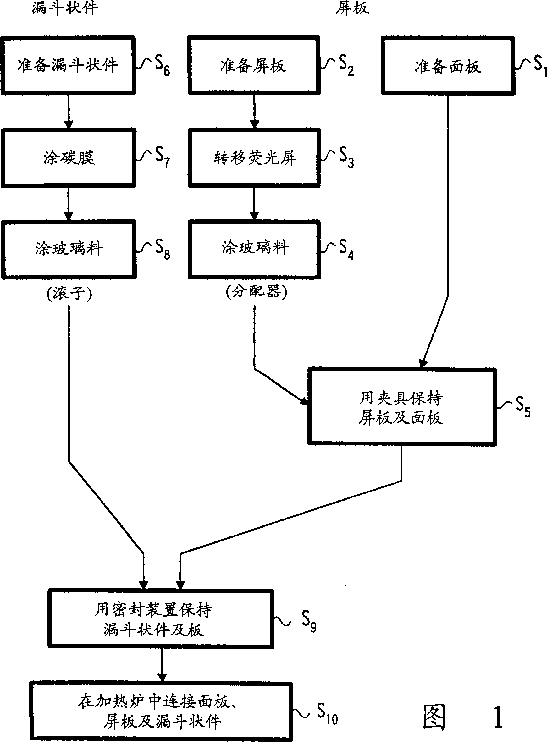
[0039] In this embodiment, a case will be described in which sealing treatment with frit is applied to the flat type glass tube assembly 6 of the flat type cathode ray tube 1 described above.

[0040] Similar to the above, the flat glass tube assembly 6 is composed of three parts, namely a first plate, in this embodiment a flat panel 2, a second plate, in this embodiment having a curved surface and a raised Partially shaped screen 3 and funnel 4 comprising a neck 7 in which the rising portion is a so-called skirt portion 3a formed along three sides.

[0041] FIG. 1 shows a flow chart of the sealing process of the flat glass tube assembly 6 . Prepare the panel 2, the screen plate 3 and the funnel 4. In step S 2 In the prepared panel 3, its inner surface will be 3Phosphor screen 3 is formed on it. Phosphor screen 3 can be formed by, for example, a transfer method....


PUM


Abstract

In a sealing apparatus used in a process for sealing a glass tube-assembly of a flat-type cathode-ray tube by frits, three of a front panel, a screen panel and a funnel can be sealed together, and the front panel can be prevented from being broken. The sealing apparatus includes a frame for properly positioning a combined assembly in which the front panel, the screen panel and the funnel are butted with each other by frits and the following sealing jig (41). The scaling jig (41) includes a holding means (42) for holding a front panel (2) and a screen panel (3) under the condition that joint surfaces of the front panel and the screen panel are butted with each other by frits. The holding means (42) is provided with a first resilient member (43) which is urged against the outer surface of the front panel (2) and a second resilient member (44) which is urged against the outer surface of the screen panel (3). A portion in which the first resilient member (43) is urged against the outer surface of the front panel (2) is provided with a member (45) whose hardness is selected to be less than that of a panel glass.

Description

technical field [0001] The present invention relates to a sealing device and a sealing method for a flat type cathode ray tube, and more particularly to a coating method and a coating device for coating a frit coating of an object to be coated, such as a glass tube assembly part of a flat type cathode ray tube . Background technique [0002] There are known reflective or transmissive flat cathode ray tubes. Reflective flat cathode ray tubes are considered, for example, for their low manufacturing costs and their high picture quality. Such as Figure 15 in (perspective view), Figure 16 (cross-sectional view) and Figure 17 (Disassembled perspective view of glass tube assembly), the flat type glass tube assembly 6 that this type of flat type cathode ray tube 1 has includes three parts, that is, a first plate, which is a panel 2 in this example; Two plates, in this case the screen 3 ; and a funnel 4 formed by sealing the electron gun 8 to the neck 7 of the funnel 4 at the ...

Claims


Application Information

Patent Timeline
Patent Type & Authority Patents(China)
IPC IPC(8): H01J9/20H01J9/26
CPCH01J9/20H01J9/261
Inventor 古井浩一三浦淳
Owner SONY CORP
Why Eureka
Try Eureka