Check patentability & draft patents in minutes with Patsnap Eureka AI!

Adhesive-tape cutting knife

A tape and cutter technology, used in printing, office supplies, sending objects, etc.

Inactive Publication Date: 2006-03-15
KOKUYO CO LTD
View PDF0 Cites 0 Cited by
  • Summary
  • Abstract
  • Description
  • Claims
  • Application Information

AI Technical Summary

Problems solved by technology

However, in these kinds of tape cutters, in recent years, although it has been considered to install a flat plate-shaped seat member with the adhesive surface exposed on the bottom surface side of the tape cutter body so as to not only adopt a lightweight structure but also pull it in a stable state. The adhesive tape is used to improve its ease of use, but the seat member is removed when it is not in use or when it is transported, or the adhesive surface is covered with a film or other skin.

Method used


Image

  • Adhesive-tape cutting knife
  • Adhesive-tape cutting knife
  • Adhesive-tape cutting knife

Examples


Embodiment Construction

[0037] An embodiment of the present invention will be described below with reference to the accompanying drawings.

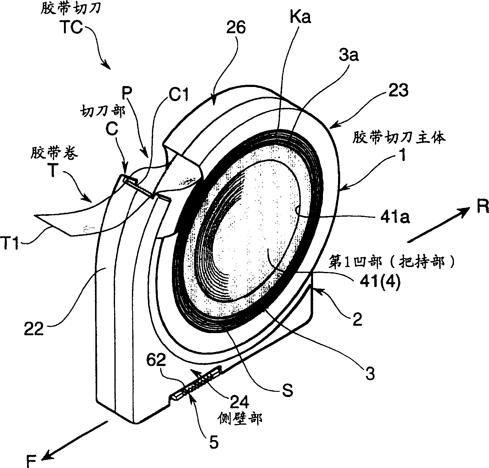
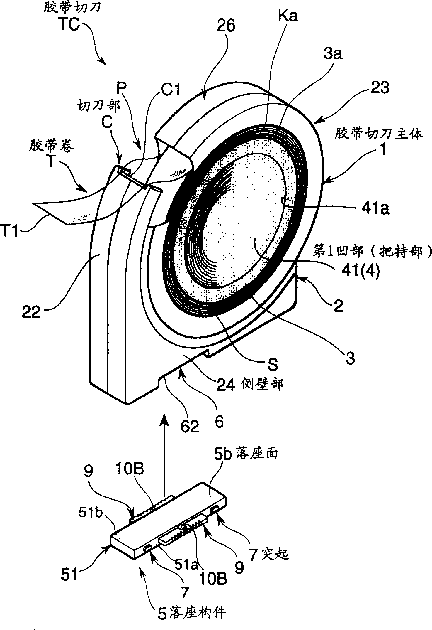
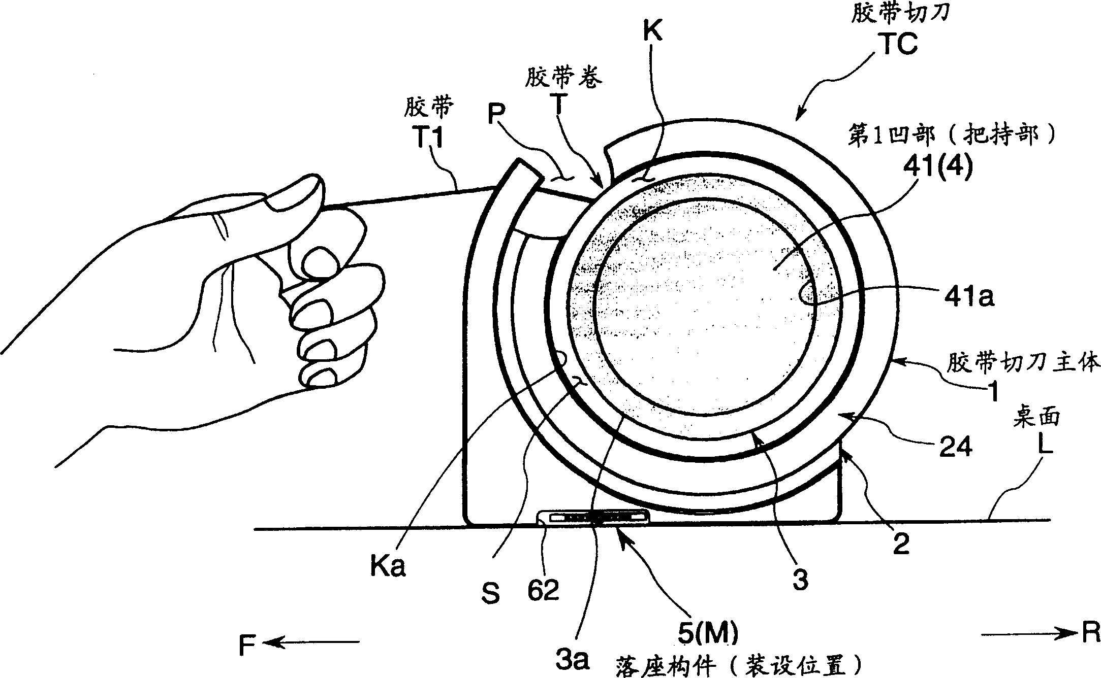
[0038] The tape cutter TC in this embodiment is used in offices, schools, or personal homes, etc., and has a cutter for holding the tape roll T rotatably and pulling out the tape T1 constituting the tape roll T and cutting it to an appropriate length. The main body 2 of the tape cutter of part C, and the seat member 5. In addition, the tape cutter TC of this embodiment is configured so that it can be used separately image 3 The first use mode in which the tape T1 is pulled out from the tape roll T by hand when the cutter portion C is positioned on the table top L as a predetermined placement surface is shown in FIG. and Figure 4 As shown in , the end portion of the aforementioned tape T1 is fixed in a state where the aforementioned cutter portion C is positioned on the lower end side, and the aforementioned tape T1 is pulled out by holding the bottom side of...


PUM


Abstract

The present invention provides a flexible and new tape cutter that serves for various embodiments of usage and good in usage circumstance in the embodiment of usage. The tape cutter is provided with a tape cutter body rotatably retaining a winding tape and provided with a cutting blade part C for drawing out a tape T1 constituting the winding tape T and cutting it to appropriate length; and a grounding member 5 having grounding surfaces 5a, 5b in which a nature of the surface is made different and which is attached to the tape cutter body 1 at an attitude that any one of these grounding surfaces 5a, 5b is selectively positioned at a bottom side of the tape cutter body 1 and can be butted to a ceiling surface L.

Description

technical field [0001] The present invention relates to an adhesive tape cutter that can rotatably support an adhesive tape roll and is suitably used in offices, schools, and the like. Background technique [0002] This kind of tape cutter has a cutter portion that pulls out the tape that constitutes the tape roll and cuts it into an appropriate length, and is configured to support the tape roll rotatably. The knife portion is positioned upward and used in the form of pulling out the tape constituting the tape roll by hand while being placed on the placement surface. In addition, recently, it is also possible to hold and stretch the main body of the tape cutter by positioning the cutter part downward and fixing the end of the tape and sandwiching the bottom part of the tape in the palm of the hand according to the above-mentioned usage form, thereby pulling out the tape cutter. A tape cutter configured as a second usage form of the aforementioned adhesive tape. However, in...

Claims


Application Information

Patent Timeline
Patent Type & Authority Patents(China)
IPC IPC(8): B65H35/07B43M17/00B43M99/00
Inventor 南和夫石崎祐辅松崎伸树香山恒斋藤未生子笹原康司
Owner KOKUYO CO LTD
Features
  • R&D
  • Intellectual Property
  • Life Sciences
  • Materials
  • Tech Scout
  • Unparalleled Data Quality
  • Higher Quality Content
  • 60% Fewer Hallucinations
Learn More