Fan rotation speed controlling system

A fan speed and control system technology, which is applied in the control system, control/regulation system, motor speed or torque control, etc., can solve the problems of prolonged time spent and increased production cost, and achieve simple adjustment actions , Save time and cost, reduce production cost

Inactive Publication Date: 2006-06-28
PROLIFIC TECH INC
View PDF0 Cites 3 Cited by
  • Summary
  • Abstract
  • Description
  • Claims
  • Application Information

AI Technical Summary

Problems solved by technology

Because it is necessary to test and adjust the product or directly eliminate the product that does not meet the specification, this will increase the production cost and lengthen the time spent in production

Method used


Image

  • Fan rotation speed controlling system
  • Fan rotation speed controlling system
  • Fan rotation speed controlling system

Examples


Embodiment Construction

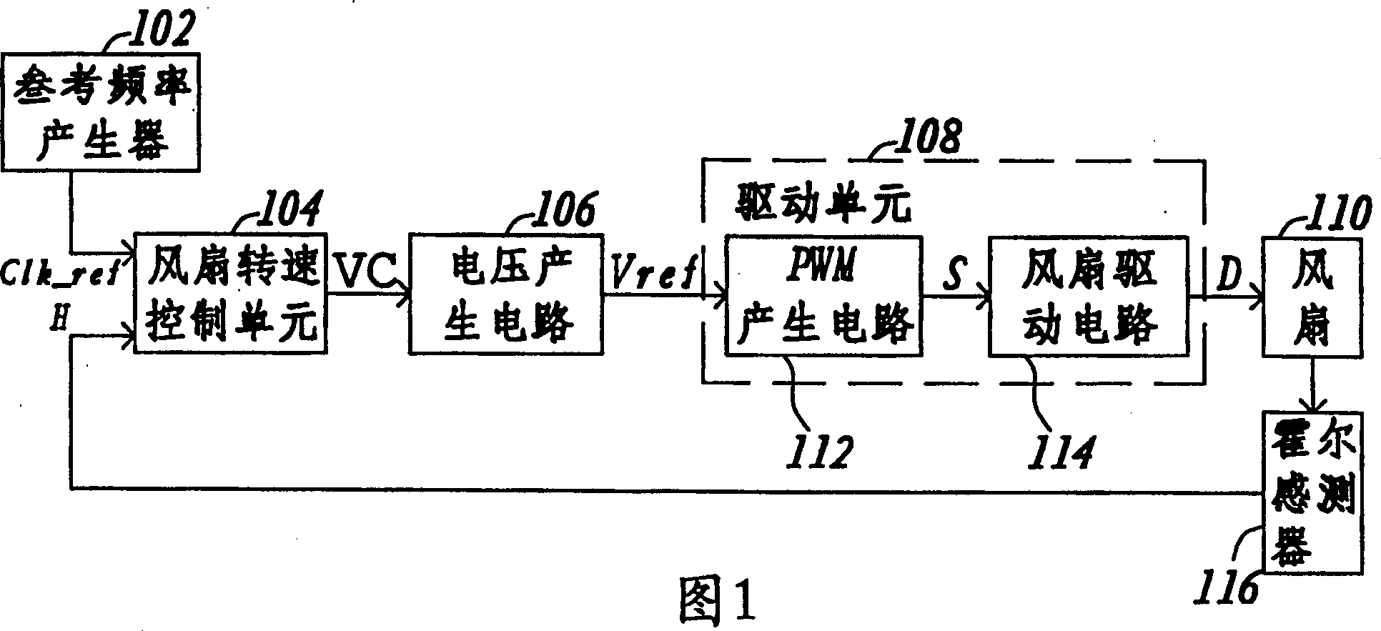
[0015] The main spirit of the present invention is to adjust the frequency of the fan speed signal corresponding to the fan speed to be close to a reference frequency by means of feedback control. The reference frequency is adjustable, and the supplier only needs to adjust the reference frequency to obtain fans with rated speeds that meet different specifications.

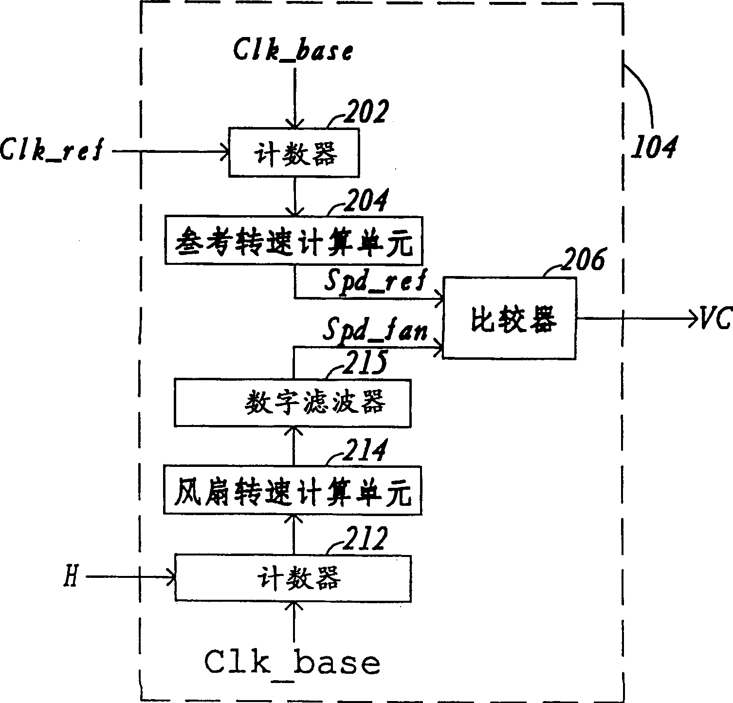
[0016] Please refer to FIG. 1, which shows a block diagram of a fan speed control system according to a preferred embodiment of the present invention. The control system of the present invention is used to control the rotating speed of the fan 110, and the rotating speed of the fan 110 corresponds to a fan rotating speed signal H. The reference frequency generator 102 is used to generate a reference clock Clk_ref. The reference clock Clk_ref has a reference frequency Fref. The fan speed control unit 104 receives the reference clock Clk_ref and the fan speed signal H at the same time, and compares the frequencies of the...


PUM


Abstract

The fan rotation speed controlling system controls fan based on one reference clock. The reference clock has one reference frequency, and the fan rotation speed is corresponding to one fan rotation speed signal. In the controlling system, the control unit compares the reference clock with the fan rotation speed signal to output one speed controlling signal; the voltage generating circuit generates one potential signal corresponding to the speed controlling signals; and the driver unit generates one drive signal to control the rotation speed of the fan based on the potential signal. The control system makes it possible to obtain different rated rotation speed with the same winding via altering the reference frequency, and this results in low production cost.

Description

Technical field [0001] The present invention relates to a control system, and in particular to a control system for the rotation speed of a fan. Background technique [0002] With the advancement of technology and the development of the computer industry, lightweight electronic products, such as notebook computers, have gradually become the mainstream of the market. In this light, thin and short electronic product, the heat dissipation capacity often affects the stability of the system, the efficiency of the product, and even the life of the product. In the computer system, in order to enable the heat generated by the computer system to quickly dissipate, the computer system is usually equipped with a fan as a heat sink, so that the computer system can operate normally under an appropriate temperature environment. [0003] Traditionally used in computer systems, fans for heat dissipation are mostly driven by brushless DC motors. In the traditional method, coils with different num...

Claims


Application Information

Patent Timeline
Patent Type & Authority Patents(China)
IPC IPC(8): H02P5/00H02P7/06G01P3/48G01P3/56G05D23/00F04D27/00H02P29/00
Inventor 许家彰陈彦仲林忠贤
Owner PROLIFIC TECH INC
Why Eureka
Try Eureka