Inkjet head
A technology of inkjet head and nozzle, applied in the direction of inking device, printing, etc., which can solve the problems of unfavorable miniaturization of highly integrated inkjet head, impossibility of small flow path structure, complicated manufacturing process, etc.
- Summary
- Abstract
- Description
- Claims
- Application Information
AI Technical Summary
Problems solved by technology
Method used
Image
Examples
Embodiment 1
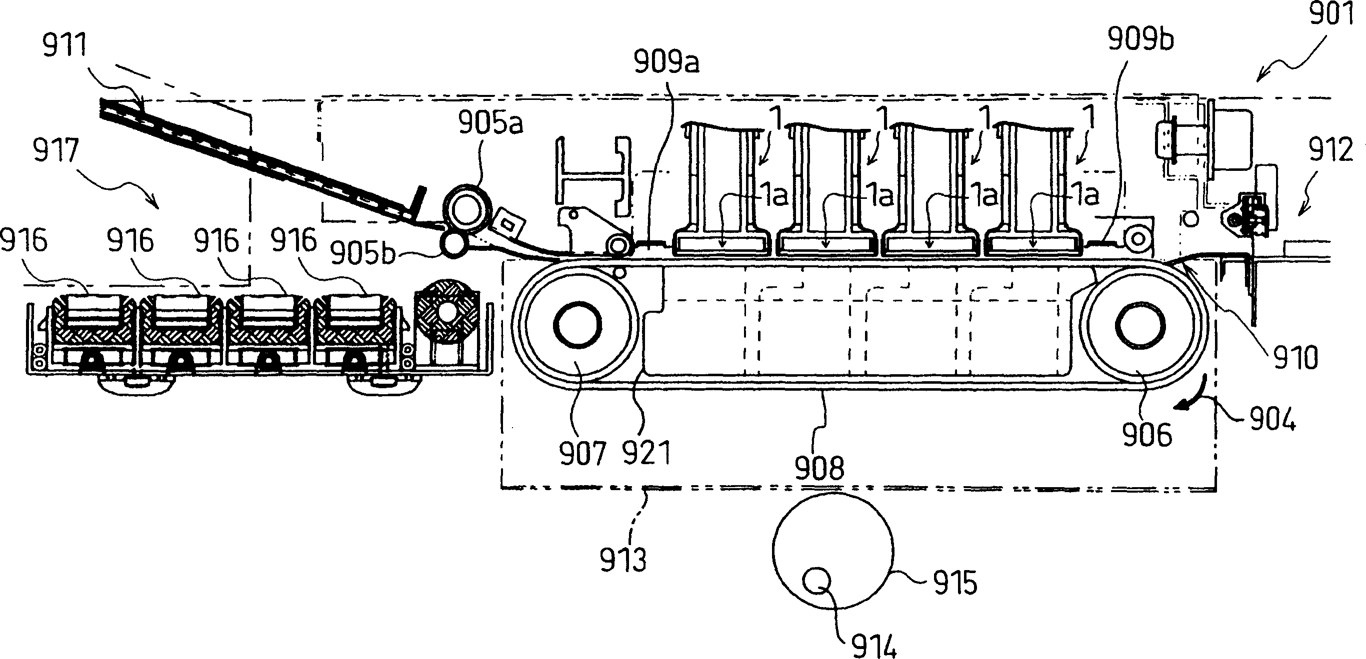
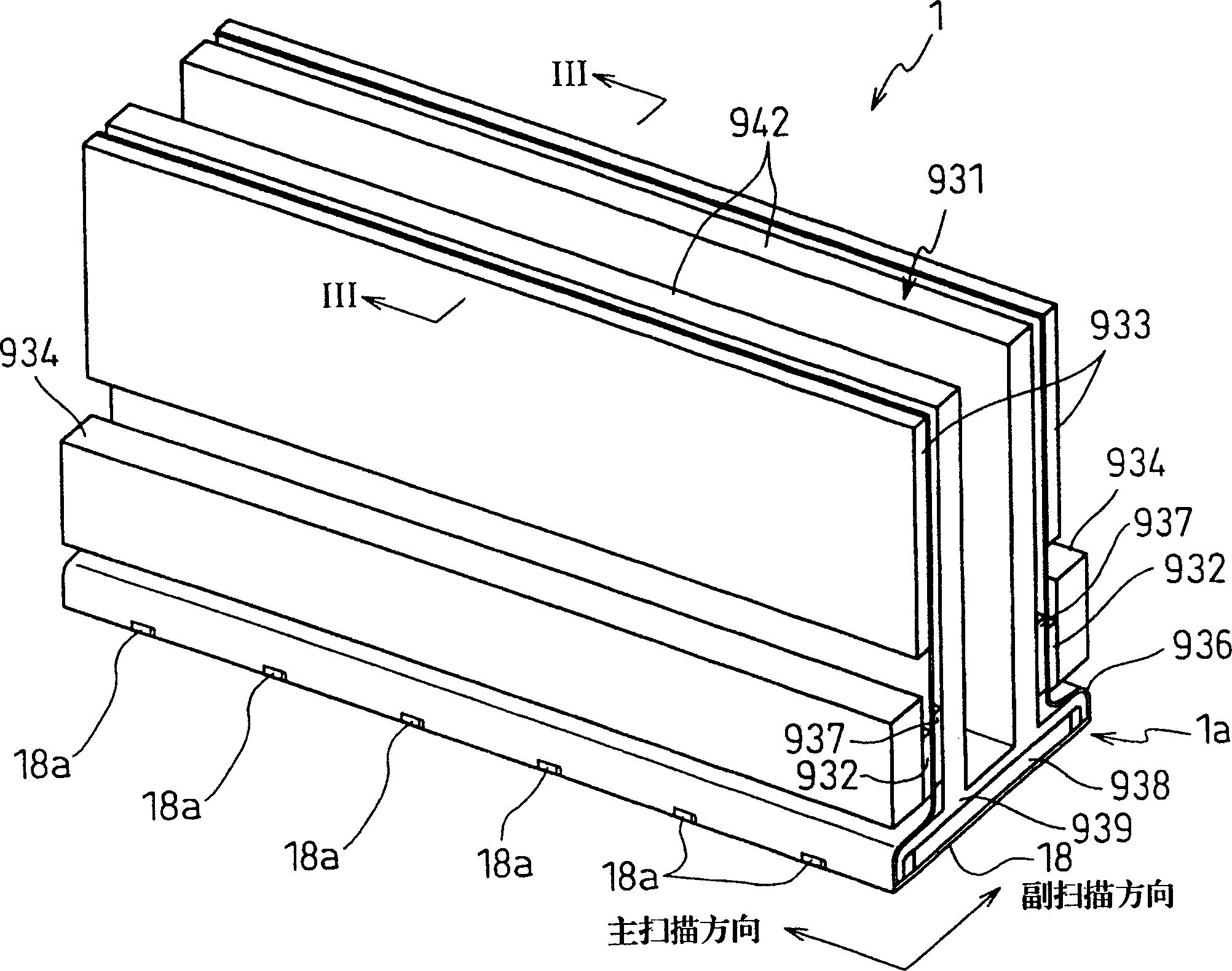
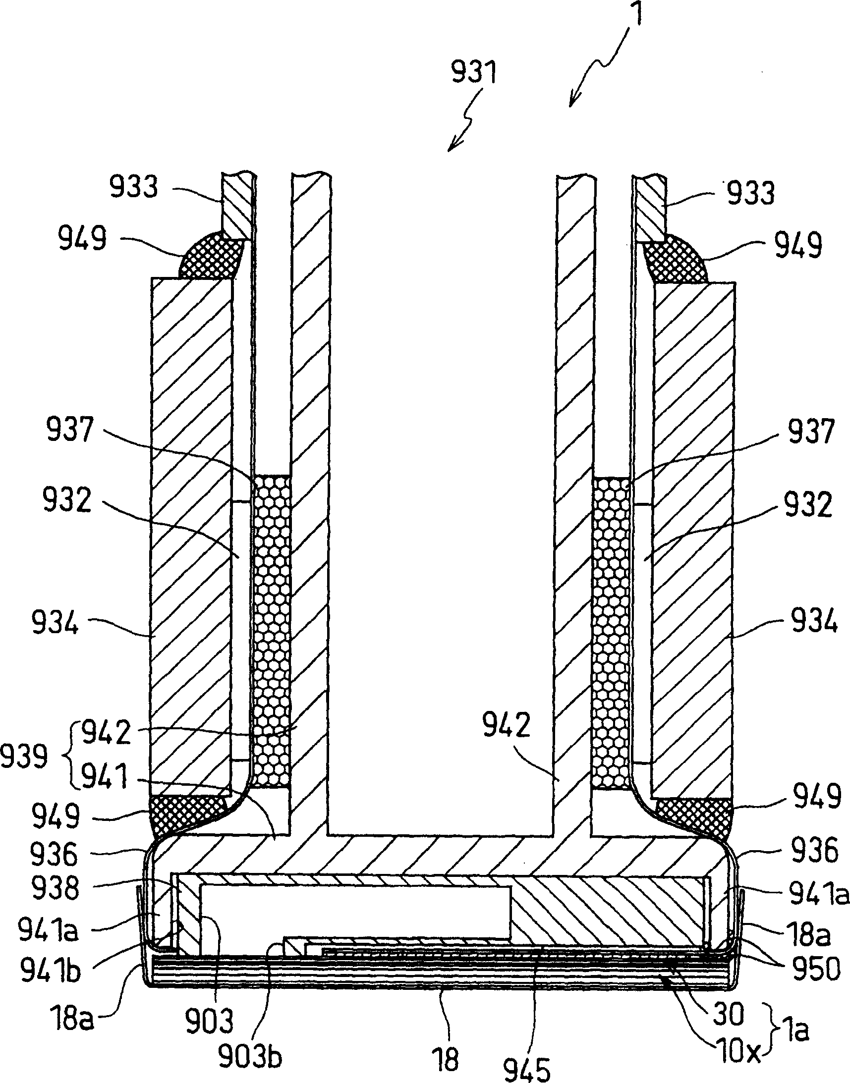
[0068] The inkjet head body 1a is composed of a cavity plate group 10 as the above-mentioned flow path unit as shown in FIG. 4 , and an actuator unit 30 fixed thereon as shown in FIG. 5 .
[0069] The cavity plate assembly 10 has a structure in which the upper surface of the ink supply port 41 is opened to supply ink from an ink cartridge (ink source) not shown. The ink supply port 41 is connected to the common ink chamber 23 formed inside the cavity plate group 10 through the ink supply channel 42 . In the middle of the ink supply flow path 42, a first filter 61 is provided.
[0070] The ink supply port 41 is arranged on the opening 903b formed by the lower part 945 of the above-mentioned base block 938 (such as image 3 shown) at the position. Therefore, the ink in the ink storage chamber 903 can be supplied to the ink supply port 41 as appropriate.
[0071] On the upper surface of the cavity plate group 10, a diamond-shaped pressure chamber 20 is recessed. Although only...
Embodiment 2
[0123] Next, Example 2 will be described. In this second embodiment, the configurations of the restricted flow path 56 and the filters 61 and 62 of the first embodiment are slightly changed.
[0124] FIG. 10 is a plan view of the ink jet head of Embodiment 2. FIG. Fig. 11 is a perspective view of the ink jet head showing a cross section along line P-P in Fig. 10 .
[0125] In the ink-jet head body 1a in the second embodiment, the cavity plate group 10y, as shown in FIG. 11, has a structure in which eight flat plates 111-118 are laminated and bonded to each other. exist Figure 12 In , the stacked structure of the cavity plate group 10y is shown in an exploded perspective view.
[0126] In addition, in this Example 2, when specifying each of the flat plates 111 to 118, they are also referred to as "0th flat plate" from the side away from the nozzle 21 . In addition, in this embodiment, the fifth flat plate 115 among the eight flat plates 111 to 118 is concentratedly describ...
Embodiment 3
[0143] Next, a third embodiment of the ink jet head will be described with reference to Figs. 14 to 19 attached.
[0144] FIG. 14 is a plan view of the ink jet head of Embodiment 3. FIG.
[0145] Fig. 15 is a perspective view of the ink jet head showing a cross section along line P-P in Fig. 14 .
[0146] Figure 16 It is an exploded perspective view showing the laminated structure of the cavity plate group of the inkjet head of Example 3.
[0147] Figure 17 It is an enlarged perspective view showing a third plate of Example 3.
[0148] Fig. 18(a) is an enlarged perspective view of main parts showing the structure of the restricted flow path of the third embodiment.
[0149] Fig. 18(b) is an enlarged perspective view of main parts showing a reference example in which no protrusion is provided in the restricted flow path.
[0150] Figure 19 An enlarged perspective view of main parts showing a modified example of a restricted flow path.
[0151] In the ink-jet head body 1...
PUM
 Abstract
Description
Claims
Application Information
 - R&D
- Intellectual Property
- Life Sciences
- Materials
- Tech Scout
- Unparalleled Data Quality
- Higher Quality Content
- 60% Fewer Hallucinations
Browse by: Latest US Patents, China's latest patents, Technical Efficacy Thesaurus, Application Domain, Technology Topic, Popular Technical Reports.
© 2025 PatSnap. All rights reserved.Legal|Privacy policy|Modern Slavery Act Transparency Statement|Sitemap|About US| Contact US: help@patsnap.com


