Pressure filter

A filter press and filter cloth technology, applied in the field of filter presses, can solve problems such as difficulty and complex structure.

Inactive Publication Date: 2006-09-13
ISHIGAKI CO LTD
View PDF2 Cites 5 Cited by
  • Summary
  • Abstract
  • Description
  • Claims
  • Application Information

AI Technical Summary

Problems solved by technology

To replace the damaged filter cloth, all the ring-shaped filter cloths hanging on the filter press must be replaced, which is a very difficult operation
In addition, the structure of the mechanism that moves the filter cloth is also complicated

Method used


Image

  • Pressure filter
  • Pressure filter
  • Pressure filter

Examples


Embodiment Construction

[0023] Hereinafter, embodiments of the filtering device of the filter press according to the present invention will be described in detail with reference to the accompanying drawings.

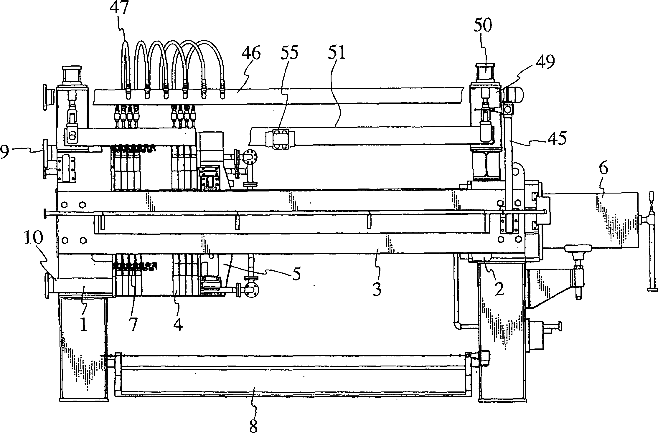
[0024] like figure 1 As shown, a pair of parallel horizontal guide rails 3 are erected on the front frame 1 and the rear frame 2. In the space between the front frame 1 and the rear frame 2, which are fixed between the left and right side walls, they support many side-by-side rails that can advance separately. And retreated filter plate 4.

[0025] Be positioned at the rear of last filter plate 4, be provided with moving head 5, it is the same with filter plate 4, also is supported on the guide rail 3, can advance and retreat. The moving head 5 is connected to the front end of the piston rod of the clamping cylinder 6 supported on the rear frame 2 , and moves forward and backward along the guide rail 3 by means of the expansion and contraction of the clamping cylinder 6 .

[0026] All side-by...


PUM


Abstract

A pressure filter is composed of many filter plates which are parallelly arranged on guide track and can be freely opened or close, and a filter cloth hung from the filter baseplates fof said filter plates, and features that the supporting rods are vertically arranged on the guide axle of said filter plates via springs, the liquid supplying plate communicated with the raw dliquid supplying channel of filter plate is arranged on said filter cloth, and the filer cloth has lower edge with weights and upper edge hung from said supporting rods to float the filter cloth above the filter plates.

Description

technical field [0001] The present invention relates to a filter press that pulls apart many side-by-side filter plates at the same time and peels off the filter cake from the filter cloth, in particular, relates to the filter cloth that is hoisted in the filter chamber of the filter plate, and the filter cloth that is hoisted in the A cleaning device that washes the filter cloth on the filter plate together, and a vibration device that vibrates the filter cloth to peel off many filter cakes from the filter cloth at the same time. Background technique [0002] JP 11-19414 discloses a filter press that will fix the upper end of the filter cloth on the filter plate and hoist it on the filter cloth supporting device in a vibrating manner. , Pull the filter plates one by one in turn, while vibrating the filter cloth or filter plate, the filter plate that peels the filter cake from the filter cloth is pulled apart in sequence. [0003] In this filter press, since the filter cake...

Claims


Application Information

Patent Timeline
Patent Type & Authority Patents(China)
IPC IPC(8): B01D25/12B01D25/21
Inventor 石垣真
Owner ISHIGAKI CO LTD
Why Eureka
Try Eureka