Optical film with sharpened bandedge

A thin-film body and optical thickness technology, applied in optics, optical components, instruments, etc., can solve the problems of not being able to improve the steepness and variation of the band edge

Inactive Publication Date: 2001-03-21
3M CO
View PDF9 Cites 19 Cited by
  • Summary
  • Abstract
  • Description
  • Claims
  • Application Information

AI Technical Summary

Problems solved by technology

However, while this method removes the reverberation, it does not improve the sharpness of the band edges, and may in fact worsen it

Method used


Image

  • Optical film with sharpened bandedge
  • Optical film with sharpened bandedge
  • Optical film with sharpened bandedge

Examples


Embodiment 1

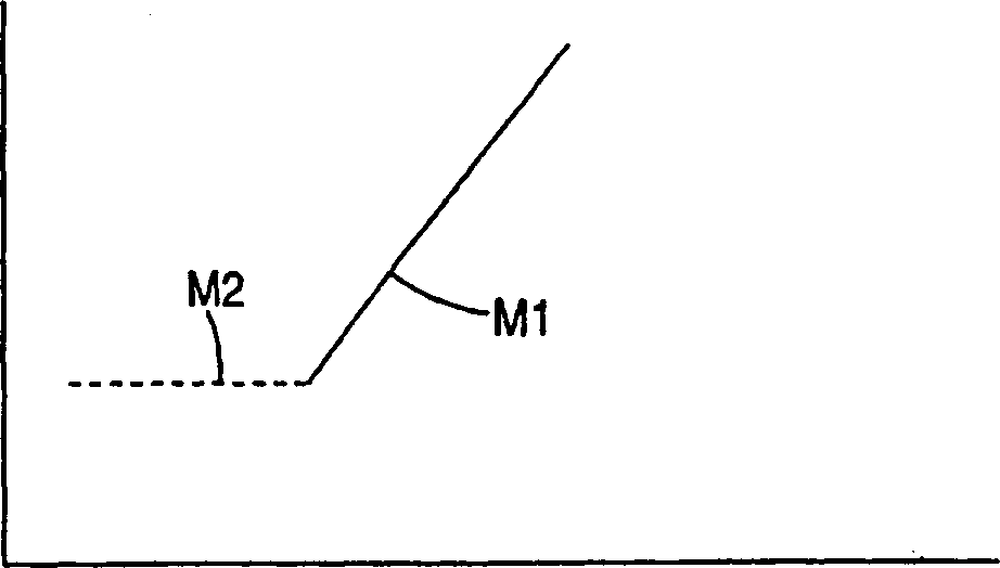
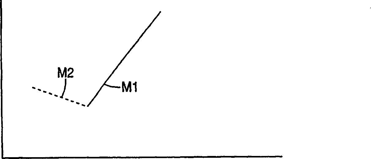
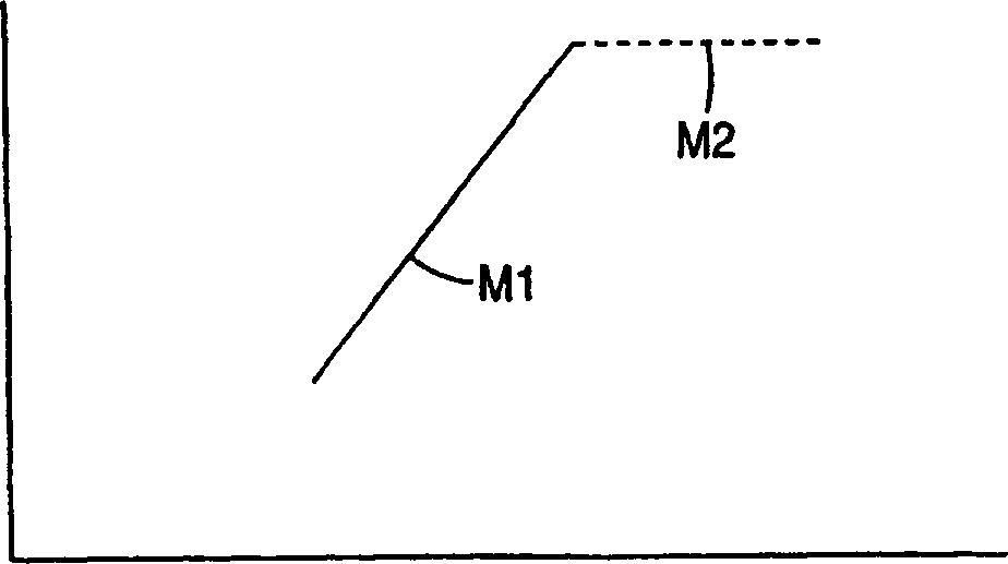
[0082] Example 1 - Inverting the Gradient

[0083] Figure E1a Shown is an example of inverting the gradient. The figure shows the bound layer thickness gradient of LTG1 and LTG2. In this case, the band-edge-steep gradient, LTG2, consists of 20 layers of alternating high- and low-index materials, the thickness of both materials increasing to maintain a 0.5 Å from the first to the last layer. f-ratio.

[0084] Another example of inverting the gradient is shown in Figure E1b . The figure shows the short-wavelength bandedge of the reflection band caused by the layer thickness gradient LTG1, and the effect of adding the inversion gradient LTG2. Adding LTG2 results in an increase in edge slope. The band edge slope without LTG2 was 1.1% / nm. When LTG2 was added, the slope increased to 1.9% / nm. The layer thickness distribution diagram is shown in Figure E1a .

Embodiment 2

[0085] Example 2 - Inverted gradient with f-ratio bias

[0086] Figure E2a Shown is an example of a stack design with an f-ratio bias reversal gradient. The figure shows a thin-film stack design with only one material component having an inversion gradient and the other material component having zero gradient in the added band-edge-steepening LTG3 stack. This combination of LTG1 and LTG3 also shows improved band edge sharpness compared to LTG1, as follows Figure E2b shown. The band edge slope with LTG3 added was 7.3% / nm.

Embodiment 3

[0087] Example 3 - Zero Gradient

[0088] This example shows the band edge steepening effect of a zero gradient stack LTG4 of two materials. The stack design of this example also produces a much steeper band edge than LTG1 alone. The band edge slope in this case was 3.6% / nm.

[0089] Figure E3a The layer thickness gradient for the combination of laminates LTG1 and LTG4 is shown. Both materials in LTG4 have zero thickness gradient and maintain a constant thickness ratio between the high and low refractive index layers. Such as Figure E3b As shown, a significant improvement was observed compared to the case of LTG1. The band edge slope is 3.6% / nm compared to the 1.1% / nm value for LTG1.


PUM


Abstract

The present invention provides reflective films and other optical bodies which exhibit sharp bandedges on one or both sides of the main reflection bands. The optical bodies comprise multilayer stacks M1 and M2, each having first order reflections in a desired part of the spectrum and comprising optical repeating units R1 and R2, respectively. At least one of the optical repeating units R1 and R2 varies monotonically in optical thickness along the thickness of the associated multilayer stack.

Description

field of invention [0001] Generally, the present invention relates to multilayer optical bodies. More specifically, the present invention relates to multilayer films with sharp reflection band edges. Background technique [0002] The use of reflective multilayer reflective films consisting of alternating layers of two or more polymers is known, for example as described in US Patent 3,711,176 (Alfrey, Jr. et al.), US Patent 5,103,337 (Schrenk et al.), WO96 / 19347 and WO95 / 17303. The reflection and transmission spectra of a particular multilayer film depend primarily on the optical thickness of the individual layers. Optical thickness is defined as the product of the actual thickness of a layer and its refractive index. Therefore, the reflection wavelength can be designed as λ by selecting the appropriate optical thickness of each layer according to the following formula M Films of infrared, visible or ultraviolet light: [0003] lambda M =(2 / M)*D r ...

Claims


Application Information

Patent Timeline
Patent Type & Authority Applications(China)
IPC IPC(8): G02B5/28
CPCG02B5/305G02B5/287G02B5/282B29D11/00788
Inventor J·A·惠特利M·F·韦伯
Owner 3M CO
Why Eureka
Try Eureka