Remote controlling system and method for liftable cages

A remote control, lift-type technology, applied in the sequence/logic controller program control, electrical program control, telephone communication, etc. Monitoring functions and other issues to achieve reliable control

A remote control, lift-type technology, applied in the sequence/logic controller program control, electrical program control, telephone communication, etc. Monitoring functions and other issues to achieve reliable control

CN1288966CInactive Publication Date: 2006-12-13YELLOW SEA FISHERIES RES INST CHINESE ACAD OF FISHERIES SCI

Image

  • Remote controlling system and method for liftable cages
  • Remote controlling system and method for liftable cages
  • Remote controlling system and method for liftable cages

Examples


Embodiment Construction

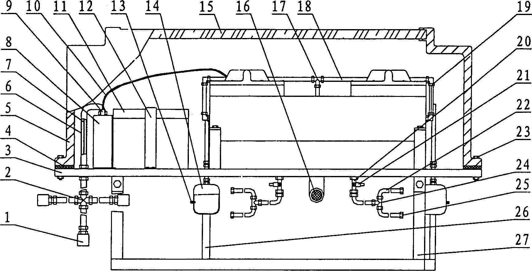
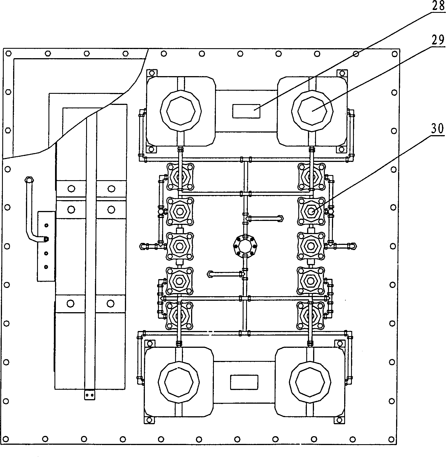
[0049] Such as figure 1 , figure 2 As shown, a lifting type net cage remote control system is composed of pressure sensors (A, B, C) 1, line pipe four-way joint 2, bottom plate 3, sealing plate 4, upper cover 5, line pipe 6, sensor Cable 7, program control box 8, terminal post 9, circuit wire 10, battery storage battery 1, battery fixing plate 12, air extraction tank limit valve 13, air extraction tank 14, solar panel 15, air vent 16, inner tube Road tee joint 17, inner pipeline 18, inner pipeline right-angle joint 19, bypass pneumatic interface 20, bypass check valve 21, air hose 22, connecting bolt 23, hose tee joint 24, soft Pipe straight-through connector 25, air extraction tank support 26, mounting frame 27, two coaxial motors 28, 4 air pumps 29, 10 electric valves 30 and user's mobile phone. Wherein, a GSM (or GPRS or CDMA) mobile communication module and a control program integrated circuit board are installed in the program control box.

[0050] The structure and o...


PUM


Abstract

A remote control system for lifting netted case is composed of floating netted casing for culturing purpose, the main flating tube with water valve and air valve, air pump, and lifting control unit consisting of casing, solar cell board, electric accumulator, motor, air pump, electric valve and program control box. Its control method features that the floating or sinking command is transmitted from mobile telephone to mobile communication module of said system for executing lifting or sinking operation.

Description

technical field [0001] The invention belongs to the remote control technology of lifting and lowering net cages in the aquaculture technology, and specifically relates to a lifting and lowering net cage capable of remote control and a control method. Background technique [0002] Utilizing the wave theory that the wave height decays proportionally with the increase of the contour of the water depth, it is an important technical measure for the net cage to resist wind and waves to sink the cage to a certain depth of water. At present, there are two types of typical large-scale lift-type net cages in the world: one is the steel structure dish-shaped net cage of Ocean SparTechnology Company in the United States. The appearance of the net cage is similar to that of a flying saucer, and the lifting and lowering of the net cage is controlled by a central column and a 5-ton balance weight, which makes the offshore installation and laying of the net cage very difficult. The other i...

Claims


Application Information

Patent Timeline
13 Dec 2006
Publication
CN1288966C
IPC
A01K61/00; G05B19/04; H04M11/00; H04B7/00
CPC
Y02A40/81
Inventors
关长涛; 黄滨