Energy-saving control method and control system for oil field pumping unit

An energy-saving control and pumping unit technology, applied in general control systems, control/regulation systems, program control in sequence/logic controllers, etc. Small and other problems, to achieve the effect of precise positioning control and high efficiency

Active Publication Date: 2022-01-25
郑州煤机智能工作面科技有限公司
View PDF0 Cites 0 Cited by
  • Summary
  • Abstract
  • Description
  • Claims
  • Application Information

AI Technical Summary

Problems solved by technology

The motor is an inductive load, and the current lags behind the voltage, resulting in reactive current, low power factor, and waste of electric energy
On the other hand, when the drive motor of the pumping unit driven by the frequency converter is in the process of braking or lowering the energy load, the motor is in the state of regenerative braking, the mechanical energy in the transmission system is converted into electrical energy by the motor, and the freewheeling diode in the frequency converter This energy is fed back to the capacitor C on the DC side of the inverter to increase the voltage on the DC side and generate a pump voltage. If this energy is not released in time, it will inevitably cause the overvoltage protection action of the inverter or cause high power in the main circuit. Device overvoltage damage
The pumped voltage dissipates energy through the resistor, which not only wastes energy, but also sometimes produces some side effects

Method used


Image

  • Energy-saving control method and control system for oil field pumping unit
  • Energy-saving control method and control system for oil field pumping unit
  • Energy-saving control method and control system for oil field pumping unit

Examples


Embodiment 1

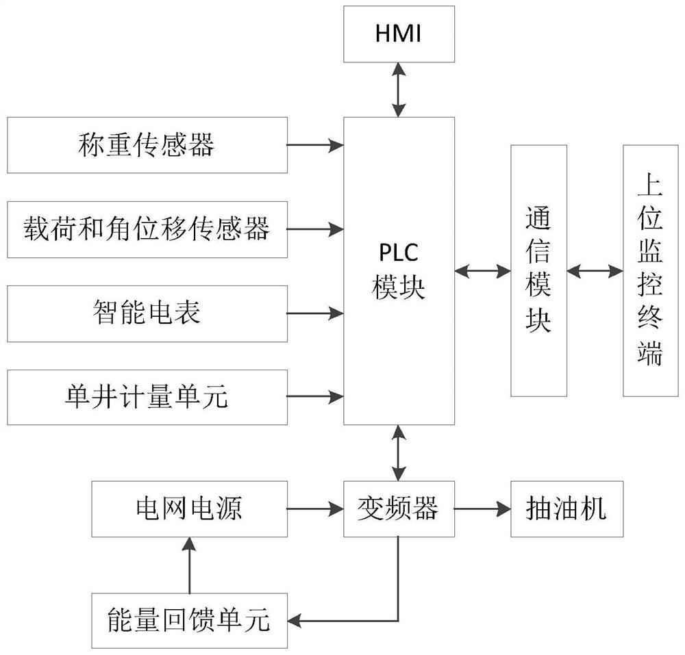
[0034] Such as figure 1 As shown, an oil field pumping unit energy-saving control system includes a PLC module, a frequency converter, an energy feedback unit, a data acquisition unit, an HMI, and an upper monitoring terminal. The PLC module, frequency converter, energy feedback unit, and HMI are set on the In the control cabinet of the control room, the frequency converter and HMI are connected to the PLC module through RS485; the data acquisition unit includes a load cell, a load and angular displacement sensor, a smart meter and a single well metering device, The sensor is arranged beside the pumping unit, connected with the oil inlet and outlet pipes, connected with the PLC module through the analog input module, and used for the detection of the continuous liquid weight (that is, the liquid output of the oil well); the load and angular displacement sensors are arranged at the pumping unit On the beam of the pumping unit, it is connected with the PLC module through the Zig...


PUM


Abstract

The invention discloses an energy-saving control method and a control system for an oil field pumping unit. After the energy-saving control mode is selected, the pumping unit is started to work when the weight of the continuous liquid is greater than the preheating weighing. After the pumping unit works for one operating cycle, Sequentially judge whether the weight of the continuous fluid is greater than the weighing at shutdown and whether the pumping unit is in a light-load state. If the weight of the continuous fluid is not greater than the weighing at shutdown or the pumping unit is in a light-load state, shut down the pumping unit and start it after one shutdown cycle For the pumping unit, if the weight of the continuous fluid is greater than the weighed after shutdown and the pumping unit is not in a light-load state, it will be judged whether the system has ended operation. If it has not ended, the pumping unit will continue to work for one operating cycle. Repeat the above steps. control mode, the invention realizes the automatic control of high efficiency and energy saving of the pumping unit.

Description

technical field [0001] The invention relates to the technical field of oilfield exploitation, in particular to an energy-saving control method and control system for an oilfield pumping unit. Background technique [0002] The pumping unit is a periodic alternating load with impact, large moment of inertia, and starts with load, so the required starting torque is relatively large, and the required motor power is also relatively large. The load of the pumping unit fluctuates greatly in one cycle. In order to meet the starting requirements, ensure that the large inertia torque of the pumping unit can be overcome when starting with load, so that there is enough overload capacity to overcome the maximum torque of the alternating load during operation. , it is required to leave enough margin when selecting the driving motor, which leads to the driving motor of the pumping unit is often in the operating state of "big horse-drawn cart", the driving motor is in a light-load state dur...

Claims


Application Information

Patent Timeline
Patent Type & Authority Patents(China)
IPC IPC(8): G05B19/05G08C17/02
CPCG05B19/058G08C17/02G05B2219/163
Inventor 张文琦董永峰杨贵柱刘珍郑贵玉权小龙韩旭景朝
Owner 郑州煤机智能工作面科技有限公司
Why Eureka
Try Eureka