Cutting insert for grooving

A technology for cutting blades and blades, which is applied in the direction of cutting tools, forming knives, turning equipment, etc. for lathes, and can solve problems such as machine interruption and shutdown

Inactive Publication Date: 2001-07-04
SANDVIK INTELLECTUAL PROPERTY AB
View PDF1 Cites 7 Cited by
  • Summary
  • Abstract
  • Description
  • Claims
  • Application Information

AI Technical Summary

Problems solved by technology

Very long, uncontrollable chips prone to machine interruptions and downtime

Method used


Image

  • Cutting insert for grooving
  • Cutting insert for grooving
  • Cutting insert for grooving

Examples


Embodiment Construction

[0016] Detailed description of the preferred embodiment

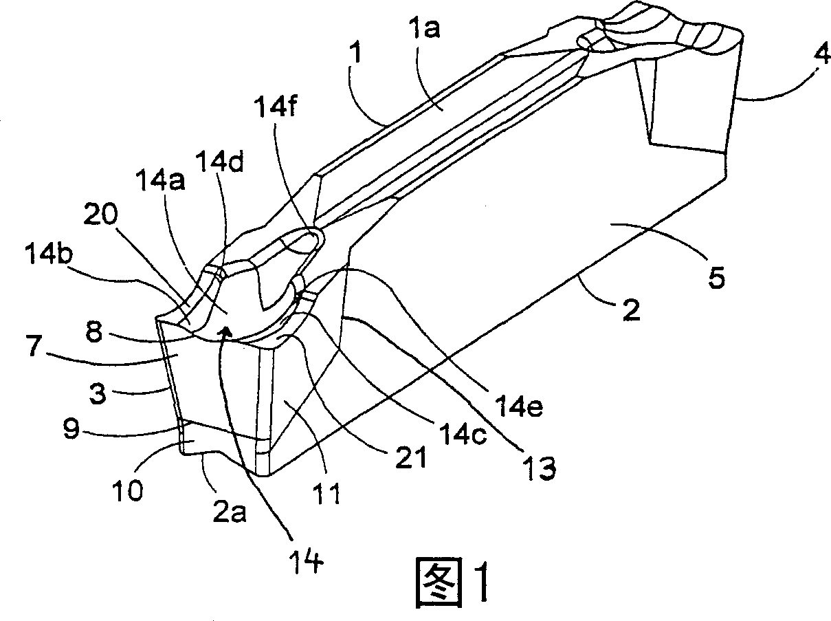
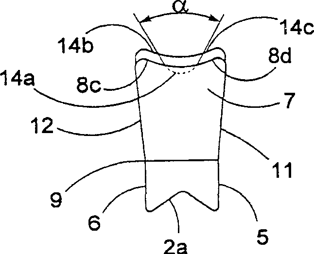
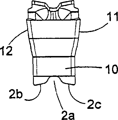
[0017] Figures 1-3 show a cutting insert for grooving according to the invention comprising a parallelepiped-shaped body having an upper surface 1, a lower surface 2, a front end surface 3, a rear end surface 4 and two opposite parallel sides 5,6. The cutting insert may or may not be coated with a carburized layer; the upper surface 1 and the lower surface 2 are respectively formed with a longitudinal concave V-shaped key groove 1a and 2a. Alternatively, cutting inserts can be Figure 2b The embodiment shown, wherein the lower support surfaces 2b, 2c have an inclination on each side of the central groove 2a, and are used in a blade-shaped tool holder in the manner described in Swedish Patent Application No. 9703434-2 Supporting corresponding inclined support surfaces, the content of said Swedish patent application No. 9703434-2 is hereby incorporated by reference. The central portion of the cutting insert is a shank ...


PUM


Abstract

A cutting insert for grooving operations includes a shank portion and a forward cutting head. The shank portion includes an upper surface, a bottom surface and side surfaces, wherein a line of intersection between the upper side and a forward clearance face forms a main cutting edge. Between the main cutting edge and a secondary cutting edge there is provided a corner cutting edge. The corner cutting edge comprises a primary curved edge with a first radius extending from the main cutting edge, and a secondary curved edge with a second radius, larger than the first radius, that extends from the primary edge to a side edge and oriented perpendicular to the main cutting edge. The cutting insert also comprises an upper side confined by two longitudinal ridges and an elongated chip forming recess therebetween.

Description

Background of the invention [0001] The invention relates to a cutting insert for grooving. More specifically, the cutting insert according to the invention is more suitable for radial grooving, although it can also be used for various axial grooving and parting off operations, as well as axial and radial turning operations. [0002] In these machining operations, chip breakage and formation play a decisive role in the processing of the product. Modern, highly productive machines place high demands on chip conveying. Very long, uncontrollable chips tend to cause machine interruptions and downtime. Therefore, chip control must be a priority and play a dominant role in tool design. [0003] Cutting inserts for grooving and parting off operations are usually held in a tool holder which is blade-shaped for creating the groove. "Insert tool holder" also includes slot milling cutters. Such cutting inserts are available, for example, from US-A-4,778,311, US-A-4,992,008, US-A-5,13...

Claims


Application Information

Patent Timeline
Patent Type & Authority Applications(China)
IPC IPC(8): B23B27/04
CPCY10T407/235B23B27/045Y10T407/25Y10T407/245B23B27/04
Inventor 佩尔·特格特斯特伦约根·威曼
Owner SANDVIK INTELLECTUAL PROPERTY AB
Why Eureka
Try Eureka