
Car stopping brake member of applied spring

A technology of brake components and spring parts, which is applied in the direction of brake components, brakes, brake cylinders, etc., and can solve problems such as difficult implementation

Inactive Publication Date: 2007-07-11
WESTINGHOUSE AIR BRAKE TECH CORP
View PDF8 Cites 1 Cited by
  • Summary
  • Abstract
  • Description
  • Claims
  • Application Information

AI Technical Summary

Problems solved by technology

[0005] A disadvantage of this prior art manual brake mechanism is that the operator must actually turn the hand wheel at least a sufficient angle to ensure that the parking brake is engaged
This in turn makes manual braking difficult to implement

Method used


Image

  • Car stopping brake member of applied spring
  • Car stopping brake member of applied spring
  • Car stopping brake member of applied spring

Examples


Embodiment Construction

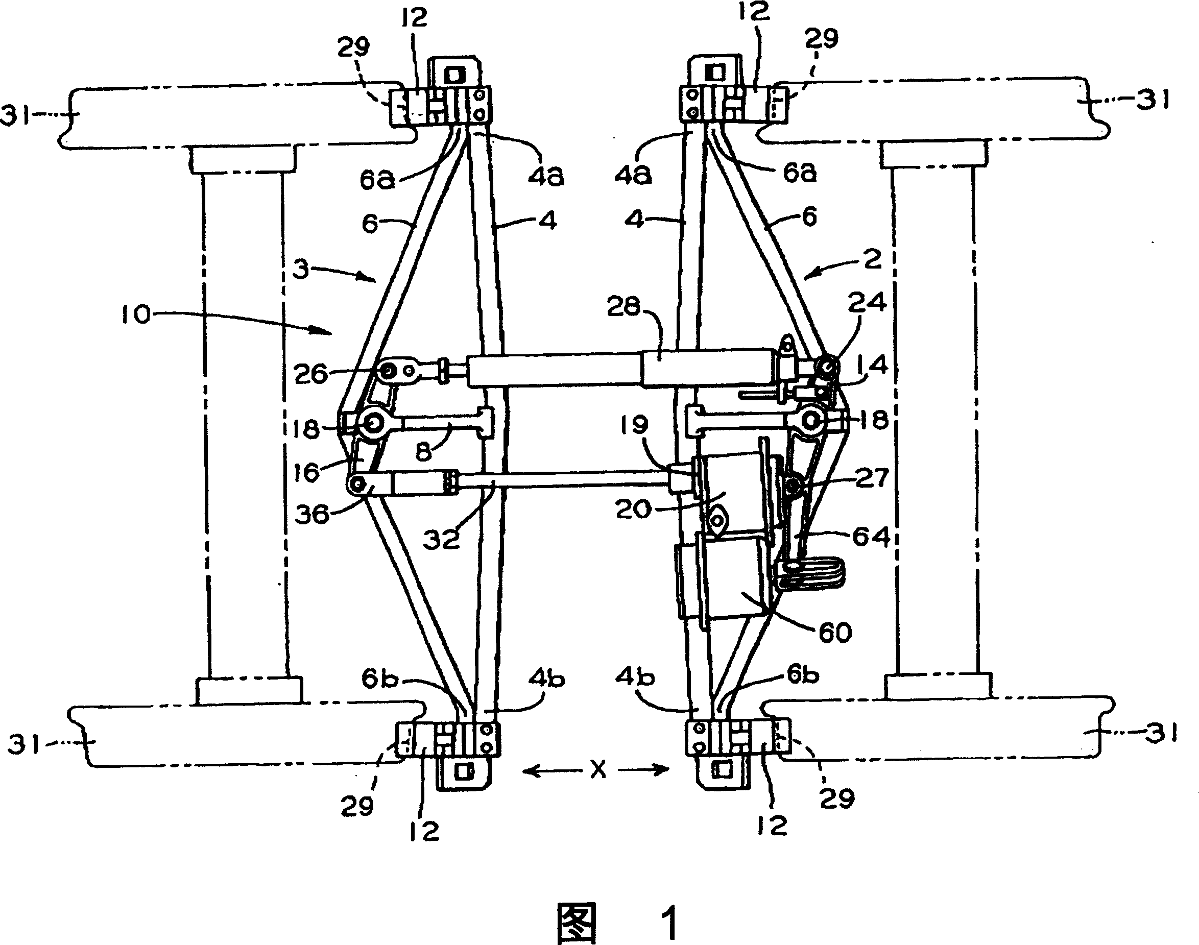
[0023] Before describing the present invention in more detail, a description of a truck mounted braking system and its function should be helpful in understanding the present invention. In addition, it should be noted that for the sake of clarity, the same parts having the same functions are denoted by the same reference numerals throughout the drawings.

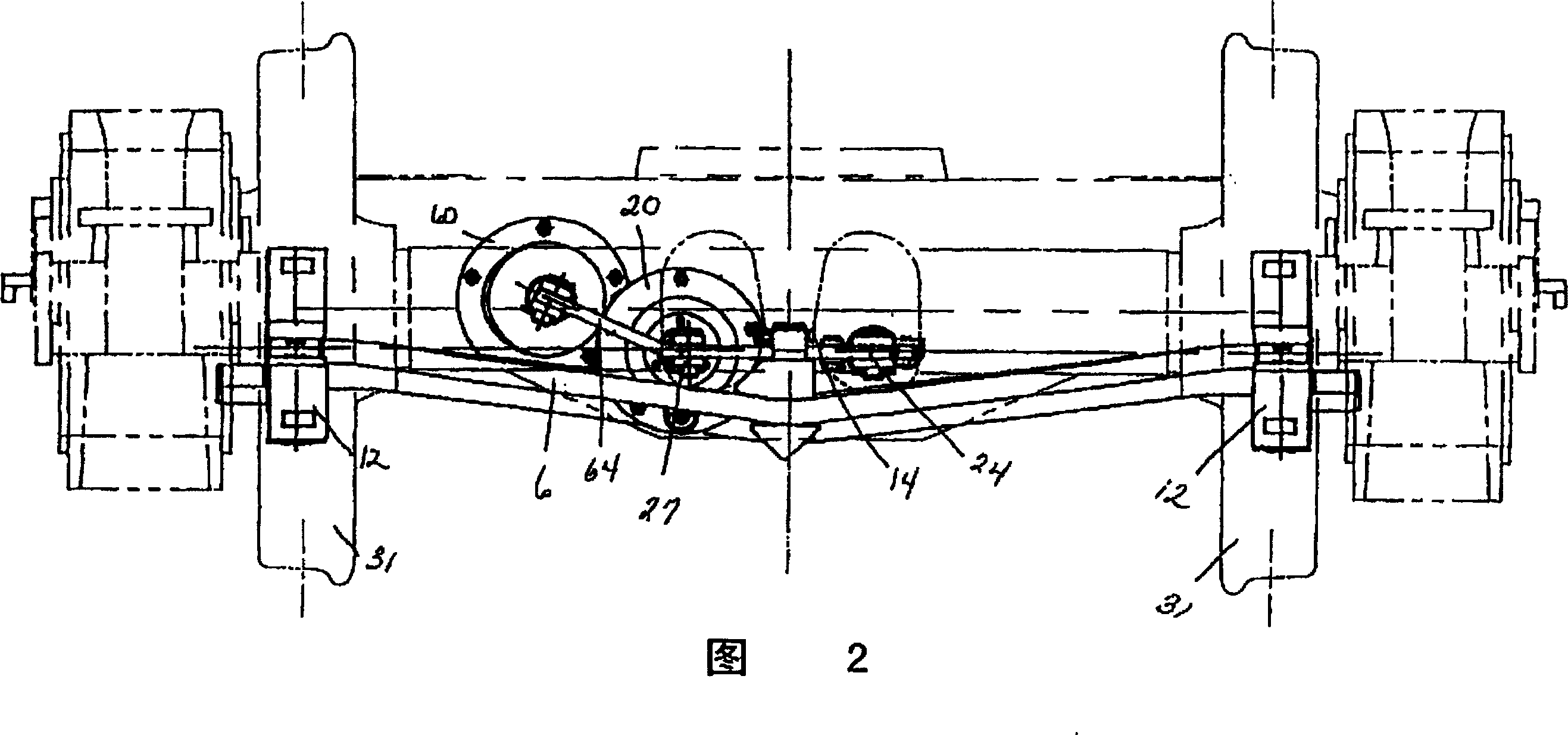
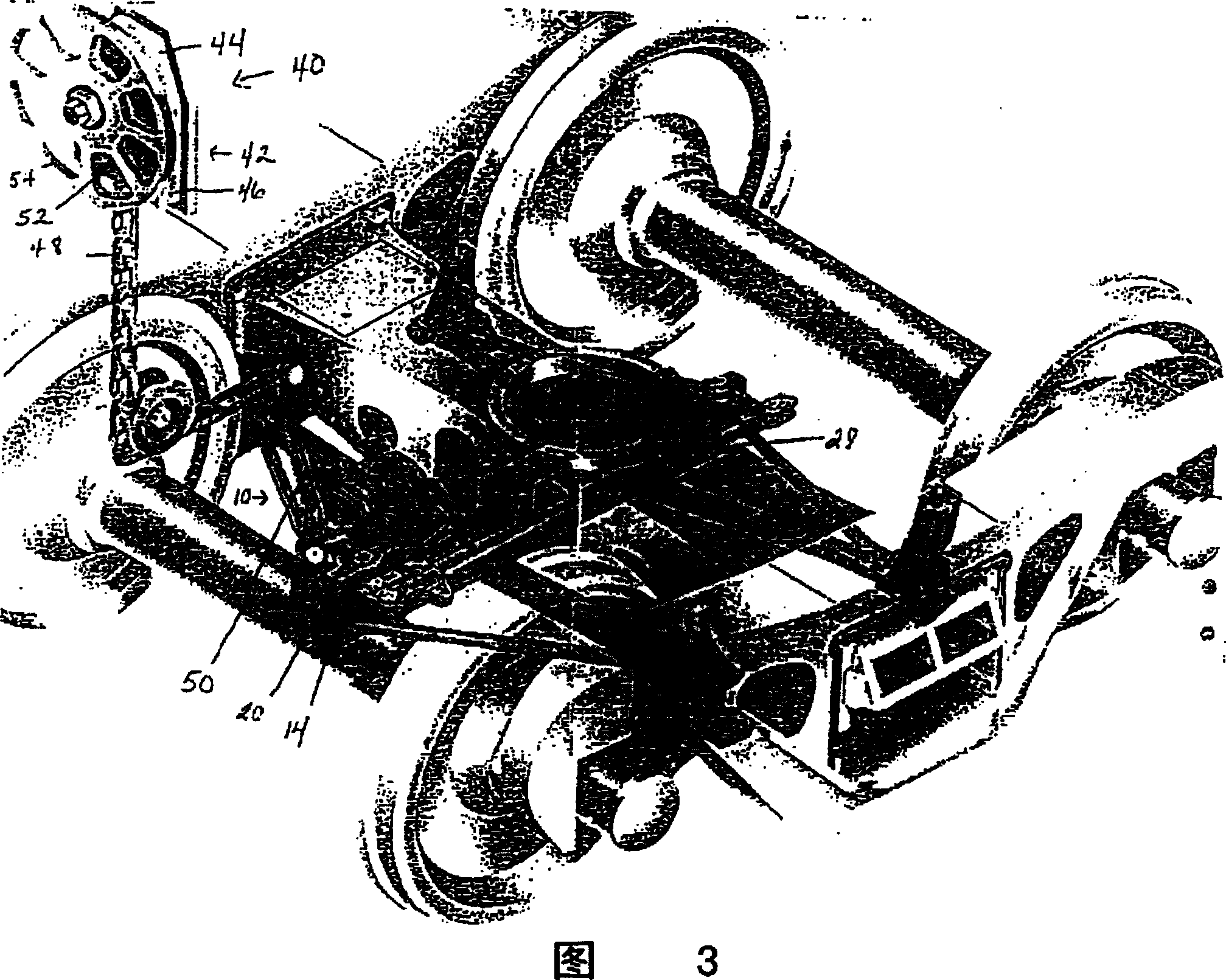
[0024] Referring now to FIG. 1, a freight car mounted brake assembly for a railroad car (not shown) is shown generally at "10". The brake assembly 10 includes substantially identical brake beams 2 and 3 each comprising a pressure member 4 , a tension member 6 and a support member 8 . The opposite ends of the pressure member 4 and the tension member 6 are permanently connected together by welding along the outer sections 4a-6a, 4b-6b at the opposite ends of the two members.

[0025] In the middle between their opposite ends, the pressure member 4 and the tension member 6 of each brake beam 2 and 3 are spaced apart sufficient...


PUM


Abstract

A spring applied parking brake assembly for a railway vehicle is provided which automatically activates upon removal of a railway car from the pneumatic braking system of the railway vehicle. The spring applied parking brake assembly comprises a casing which is mounted on or within the braking system, typically alongside the air cylinder. This casing contains a spring member and a piston assembly, both of which are mounted for longitudinal movement within the casing upon the application and / or removal of pneumatic pressure within the casing. The piston assembly includes a piston rod which is associated with the force transfer lever of the braking system such that upon a removal of pneumatic pressure within the casing, longitudinal movement of the piston rod causes this force transfer lever to rotate and apply a force to at least one force transmitting member in the vehicle braking system to initiate a brake application. An arrangement or system for installing the spring applied parking brake assembly within a railway vehicle braking system is also provided.

Description

technical field [0001] This invention relates generally to parking brake assemblies for use in railway vehicle braking systems, and more particularly to spring-applied parking brake assemblies for use in railway vehicle braking systems that do not use air actuation in railway vehicle braking systems. Brake assemblies, and even more specifically relate to spring applied parking brake assemblies for use in rail vehicle truck mounted brake assemblies. Background technique [0002] As is well known in the railroad industry, when railroad cars are disengaged from a train and parked on a side rail or in a parking lot, the hand brake or parking brake is applied on at least some of the cars to prevent unwanted movement of the cars. unwanted or unwanted movement. A common railroad car manual braking system consists of a device that manually applies one or more brake pads to and from the bias by turning a handwheel or swinging a ratchet handle on a manual braking mechanism Placed on...

Claims


Application Information

Patent Timeline
IPC IPC(8): B61H11/00B61H11/02B61H11/06B60T13/38B60T11/06B60T13/04B60T13/26B60T17/08B61H13/20B61H13/36
CPCB60T13/04B60T17/085B60T13/261B60T11/06B61H13/36
Inventor 瓦吉赫·卡恩乔斯科特·内切克
Owner WESTINGHOUSE AIR BRAKE TECH CORP
Learn More