Eureka AIR delivers breakthrough ideas for toughest innovation challenges, trusted by R&D personnel around the world.

Optical-head apparatus

A technology of optical head and light source, which is applied in the direction of integrated optical head device, beam guiding device, optical recording head, etc., which can solve the problems of high manufacturing cost, low sealing performance and rough bonding surface of metal molds

Inactive Publication Date: 2007-08-15
SANKYO SEIKI MFG CO LTD
View PDF3 Cites 0 Cited by
  • Summary
  • Abstract
  • Description
  • Claims
  • Application Information

AI Technical Summary

Problems solved by technology

For this reason, the machining accuracy (mold accuracy) of the reference surface of the frame must also be high-precision, so a lot of labor is required to manufacture the metal mold of the frame.
Especially when multiple molds are required, since the precision of these molds must be consistent, there is a problem that the manufacturing cost of metal molds is very high
[0004] When a frame made of resin is used, the position of the optical element mounted on the frame will fluctuate more than that of a metal frame due to resin expansion caused by temperature difference, which will reduce the reliability of the device.
In addition, since the sealing performance of the resin frame due to the adhesive is lower than that of the metal frame, it is necessary to add a process of roughening the bonding surface.

Method used


Image

  • Optical-head apparatus
  • Optical-head apparatus
  • Optical-head apparatus

Examples


Embodiment Construction

[0026] An embodiment to which the optical head apparatus of the present invention is applied will be described below with reference to the accompanying drawings.

[0027] (overall composition)

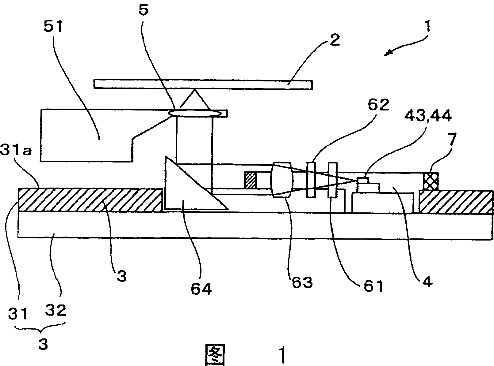
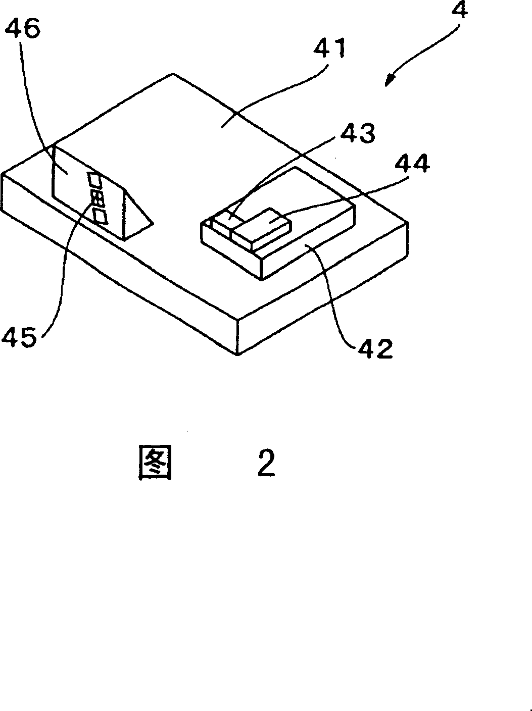
[0028] FIG. 1 is a cross-sectional view showing the optical head device of the present invention, and FIG. 2 is a perspective view showing a light-receiving and light-emitting element in the optical head device in FIG. 1 . Description will now be made with reference to these figures. The optical head device 1 of the present embodiment is a two-wavelength optical head device for recording and reproducing information on an optical recording medium 2 such as CD or DVD, and using a laser beam with a wavelength of 650 nm and a laser beam with a wavelength of 780 nm. Various components are mounted on the base 3 composed of a circuit board 31 made of metal such as aluminum and a base frame 32 made of metal stacked on top of each other.

[0029] The base 3 is provided with a main shaft that ...


PUM


Abstract

The invention proposes an optical head device, in which the accurate positioning for optical components is allowed by using a frame body consisting of a photosensitive glass mounted on a base. In the optical head device 1, the frame body 7 consisting of the U-shaped photosensitive glass is mounted on the base 3 having the constitution laminated with a metallic wiring substrate 31 and a metallic base frame 32, and a light receiving / emitting element 4, 1st and 2nd optical elements 61, 62 and a collimator lens 63 are positioned with this frame body 7. For the optical elements 61, 62, 63 held by the frame body 7, the fine adjustment for the mounting position is allowed from the rear side of an opening part through this opening part opened on the base 3. Consequently, the accurate positioning is attained for each optical element by the simple work.

Description

technical field [0001] The present invention relates to an optical head device for recording and reproducing optical recording media such as CD and DVD. Specifically, it relates to the positioning structure of the light source, light receiving element and various optical elements in the optical head device. Background technique [0002] An optical head device for recording and reproducing optical recording media such as CDs and DVDs includes a semiconductor laser as a laser light source, and a photodetector for receiving light emitted from the semiconductor laser and reflected light reflected by the optical recording medium. Various optical elements such as lenses for guiding outgoing light or reflected light between these semiconductor lasers and photodetectors, and objective lenses for focusing outgoing light guided by the optical elements on an optical recording medium. These parts are mounted on a frame made of a metal material such as aluminum or a material such as res...

Claims


Application Information

Patent Timeline
Patent Type & Authority Patents(China)
IPC IPC(8): G11B7/135G02B7/00G11B7/00G11B7/12G11B7/123G11B7/125G11B7/1275G11B7/22
CPCG11B7/1205G11B2007/0006G11B7/1275G11B7/22G11B7/123
Inventor 森山克也石原久宽竹村政夫
Owner SANKYO SEIKI MFG CO LTD
Why Eureka
Eureka Blog
Learn More