
Combined type valve with double fluid channels in use for reciprocating pump

A reciprocating pump, dual-flow technology, used in control valves, valve devices, pump components, etc., can solve the problems of small flow area, short valve plate life, and difficulty in exhausting gas, so as to increase the flow area, reduce Valve closing acceleration and impact force, the effect of reducing self-weight

Inactive Publication Date: 2007-08-22
ZHEJIANG UNIV OF TECH
View PDF7 Cites 0 Cited by
  • Summary
  • Abstract
  • Description
  • Claims
  • Application Information

AI Technical Summary

Problems solved by technology

[0006] In order to overcome the deficiencies of the combined valve for reciprocating pumps in the prior art, such as small flow area, poor cavitation performance, short valve plate life, poor guidance, and difficulty in exhausting gas, the present invention provides a large flow area, cavitation Double-channel combined valve for reciprocating pumps with good performance, long service life of the valve plate, long guide, and ensuring that the gas in the pump liquid cylinder can be exhausted

Method used


Image

  • Combined type valve with double fluid channels in use for reciprocating pump
  • Combined type valve with double fluid channels in use for reciprocating pump

Examples


Embodiment 1

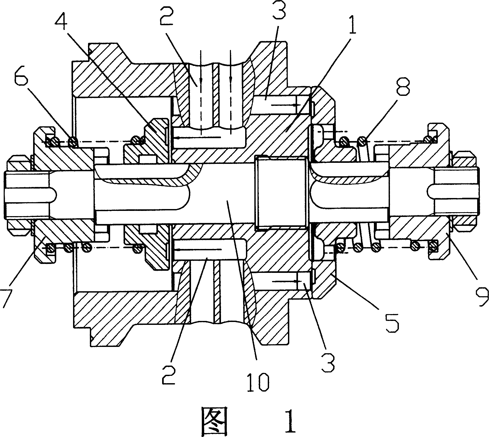
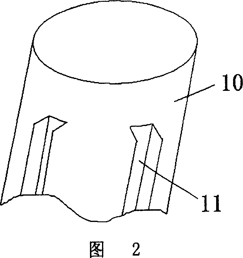
[0018] Referring to Fig. 1 and Fig. 2, a dual-channel combination valve for a reciprocating pump includes a valve body 1, and the valve body is provided with an inlet valve flow channel 2 communicating with the inlet of the reciprocating pump and a channel communicating with the outlet of the reciprocating pump. Outlet valve channel 3, the outlet of the inlet valve channel 2 is equipped with an inlet valve plate 4 for opening and closing the inlet valve channel, and the outlet of the outlet valve channel 3 is equipped with an inlet valve plate 4 for opening and closing the inlet valve channel. Close the outlet valve plate 5 of the outlet valve flow channel, the inlet valve plate 4 is connected with the inlet spring seat 7 through the inlet spring 6, the space in front of the inlet valve plate 4 is a reciprocating medium cavity, and the outlet valve plate 5 The outlet spring 8 is connected to the outlet spring seat 9, the space in front of the outlet valve plate 5 is a reciproca...

Embodiment 2

[0022] Referring to FIG. 1 , the inflow and outflow ports of the outlet valve channel 3 are located outside the outflow port of the inlet valve channel 2 , so that the gas in the pump cylinder can be exhausted. Especially when the outlet valve channel 3 is located at the outermost side of the valve body 1, the effect is better.

[0023] The rest of the structure and implementation are the same as in Embodiment 1.

Embodiment 3

[0025] The inlet spring seat and the outlet spring seat are also provided with flow passages to further increase the flow area. The axial groove, of course, the structure and shape of the flow channels on the inlet spring seat and the outlet spring seat are not limited thereto.

[0026] The rest of the structure and implementation are the same as in Embodiment 1.


PUM


Abstract

The present invention relates to a double-channel combined valve for reciprocating pump. Said double-channel combined valve includes the following components: valve body, inlet valve flow channel, outlet valve flow channel, inlet valve plate, outlet valve plaet, inlet spring and inlet spring seat, reciprocating pump medium cavity, outlet spring and outlet spring seat, and reciprocating pump liquid discharge cavity.

Description

(1) Technical field [0001] The invention relates to a combined valve for a reciprocating pump, in particular to a double-channel combined valve for a reciprocating pump. (2) Background technology [0002] The reciprocating pump is a very important fluid machine. The product sucks and discharges the medium by means of the inlet and outlet one-way valves. Combination valve is a special valve group for reciprocating pumps. [0003] The structure of the existing combined valve for reciprocating pumps is: including a valve body, the valve body is provided with an inlet valve flow channel connected with the reciprocating pump inlet and an outlet valve flow channel connected with the reciprocating pump outlet, the inlet valve flow channel An inlet valve plate for opening and closing the flow path of the inlet valve is installed at the outlet of the outlet valve, and an outlet valve plate for opening and closing the flow path of the outlet valve is installed at the outlet of the fl...

Claims


Application Information

Patent Timeline
Patent Type & Authority Patents(China)
IPC IPC(8): F04B53/14F16K15/18
Inventor 张生昌陈明海周深彪牟介刚邓鸿英郑水华
Owner ZHEJIANG UNIV OF TECH
Learn More