

Inner magnetic shield and cathode-ray tube
A magnetic shielding cover and cathode ray technology, applied in cathode ray tubes/electron beam tubes, discharge tubes, eliminating unnecessary electromagnetic effects, etc., can solve problems such as suppression of mis-landing
- Summary
- Abstract
- Description
- Claims
- Application Information
AI Technical Summary
Problems solved by technology
Method used
Image

Examples
Embodiment 1
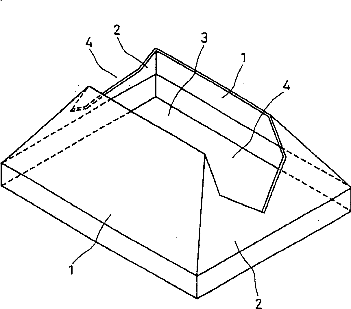
[0030] figure 1 It is a perspective view of the internal magnetic shield related to Embodiment 1 of the present invention.
[0031] The inner magnetic shield of this embodiment has a pair of substantially trapezoidal long sidewalls 1 and a pair of substantially trapezoidal short sidewalls 2, which constitute a part of a square cone. In the center of the inner magnetic shield, an opening 3 is surrounded by the long side wall 1 and the short side wall 2 . In the internal magnetic shield, the side with the narrow opening ( figure 1 The upper side in the middle) is the side of the electron gun and the side with the wide opening ( figure 1 The lower side in ) is the fluorescent screen side installed in the cathode ray tube, and the electron beams pass through the opening 3 . On the short side wall 2, a notch 4 is formed from the upper end on the electron gun side toward the phosphor screen side.
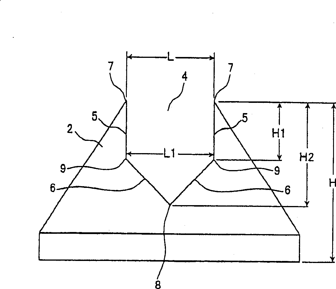
[0032] figure 2 for figure 1 A side view of the short side wall 2 of the i...
Embodiment 2
[0041] Figure 7 It is a perspective view of the inner magnetic shield related to Embodiment 2 of the present invention.
[0042] The internal magnetic shield of this embodiment includes a pair of substantially trapezoidal long sidewalls 1 facing opposite and a pair of substantially trapezoidal short sidewalls 11 facing oppositely, which combine to form a part of a square cone. An opening 3 surrounded by the long side wall 1 and the short side wall 11 is formed in the center of the inner magnetic shield. On the short side wall 11, an opening 12 is formed from the electron gun side toward the phosphor screen side.
[0043] The shape of the cutout 12 formed by the short side wall 11 of the second embodiment is different from the shape of the cutout 4 of the first embodiment.
[0044] Figure 8 for Figure 7 A side view of the short side wall 11 of the inner magnetic shield. Figure 8 The up and down direction of the tube is consistent with the tube axis direction of the cat...
Embodiment 3
[0052] Figure 10 It is a sectional view of the color cathode ray tube 30 of the present invention in the vertical direction passing through the tube axis.
[0053] The tube shell 33 is formed by combining the glass screen 31 and the funnel 32 . A substantially rectangular fluorescent screen 34 is formed on the inner surface of the glass screen 31 . A color selection electrode (such as a shadow mask) 35 is mounted on a frame 36 in a spaced and opposite arrangement from the fluorescent screen 34 . The frame 36 is fixed to the glass screen 31 by being hung on the screen pins (not shown) provided on the inner surface of the glass screen 31 through the leaf spring-shaped elastic supporting member (not shown in the figure) on its outer periphery. The electron gun 37 is installed in the neck of the funnel 32 . An internal magnetic shield 40 is attached to the periphery of the frame 36 on the electron gun 37 side. A deflection coil 39 is installed outside the funnel 32 to deflect...
PUM
 Abstract
Description
Claims
Application Information