Particulate burning purifying catalyst

An oxidation catalyst and catalyst technology, applied in physical/chemical process catalysts, metal/metal oxide/metal hydroxide catalysts, dispersed particle separation, etc., can solve the problems of fuel consumption reduction, particle filter deterioration, and large exhaust gas pressure loss And other issues

Inactive Publication Date: 2002-12-18
TOYOTA JIDOSHA KK
View PDF1 Cites 2 Cited by
  • Summary
  • Abstract
  • Description
  • Claims
  • Application Information

AI Technical Summary

Problems solved by technology

[0005] However, under the actual operation of the diesel engine, the temperature of the exhaust gas is often lower than 350°C. At the above-mentioned ignition temperature of about 350°C to 400°C, the particles cannot be completely burned and removed, and the pressure loss of the exhaust gas passing through the filter is large, resulting in combustion. Barriers to fee reduction
Moreover, once a large number of remaining particles are burned, the temperature of the particle filter exceeds about 800°C, and there is a problem of premature deterioration of the particle filter.

Method used


Image

  • Particulate burning purifying catalyst
  • Particulate burning purifying catalyst
  • Particulate burning purifying catalyst

Examples


Embodiment 1

[0047] Add 20 parts by mass of WO to 91 parts by mass of zirconium hydroxide powder 3 The conversion concentration is 50% by mass of ammonium metatungstate aqueous solution, mixed and dried at 80°C overnight, then sintered at 650°C for 2 hours to obtain tungstic acid / zirconia (WO 3 / ZrO 2 )powder.

[0048] In addition, 85 parts by mass of 40% by mass barium acetate aqueous solution was added to 100 parts by mass of γ-alumina powder, mixed, dried overnight at 80°C, and then sintered at 500°C for 1 hour to obtain Ba / γ-alumina powder.

[0049] In these WO 3 / ZrO 2 To 100 parts by mass of powder and 100 parts by mass of Ba / γ-alumina powder, 60 parts by mass of aluminum nitrate solution with a concentration of 40 mass%, 40 parts by mass of ceria-zirconia powder, and 200 parts by mass of water were added, and mixed with a ball mill 8 hours.

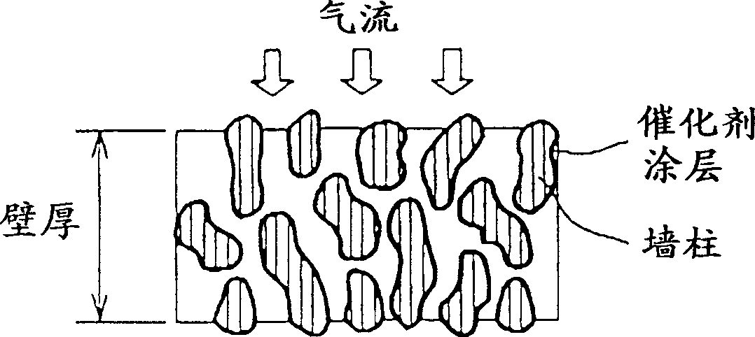
[0050] The resulting slurry is coated on the monolithic substrate, dried and sintered at 650°C for 1 hour to form a WO containing WO on t...

Embodiment 2

[0053] Obtain WO equally with embodiment 1 3 / ZrO 2 powder.

[0054] On the one hand, 5 parts by mass of Fe was impregnated with respect to 100 parts by mass of γ-alumina powder, dried overnight at 80°C, and then sintered at 500°C for 1 hour to obtain Fe / γ-alumina powder.

[0055] In these WO 3 / ZrO 2 To 100 parts by mass of powder and 100 parts by mass of Fe / γ-alumina powder, 60 parts by mass of aluminum nitrate solution, 40 parts by mass of ceria-zirconia powder, and 200 parts by mass of water were added in the same manner as in Example 1, and mixed by a ball mill 8 hours.

[0056] The resulting slurry is coated on the monolithic substrate, dried and sintered at 650°C for 1 hour to form a WO-containing substrate on the monolithic substrate. 3 / ZrO 2 powder and layers of Fe / γ-alumina powder.

[0057] Then, impregnate dinitrosated diammine Pt aqueous solution and Rh nitrate aqueous solution in the same manner as in Example 1, and sinter at 500° C. for 1 hour to obtain a...


PUM


Abstract

To provide a particulate purification catalyst that easily burns particulates trapped in a particulate filter of a diesel vehicle at a lower temperature than conventional ones. The structure of this particulate catalyst is characterized in that it is formed by including a NO oxidation catalyst formed on a first carrier supported by a catalyst component and an NO2 decomposition catalyst formed on a second support supported by a catalyst component. Preferably, noble metals such as NO oxidation catalyst platinum are supported on the first carrier of tungstic acid / zirconia acidic substances, NO2 decomposition catalysts are selected from the transition metal group catalyst components supported on the second carrier such as titanium oxide, or NO2 decomposition catalysts At least one metal selected from alkali metals and alkaline earth metals and noble metals such as platinum are supported on a second support such as titanium oxide.

Description

Background technique [0001] The present invention relates to a catalyst for combusting and removing soot-like particles (carbonaceous fine particles) contained in exhaust gas discharged from internal combustion engines such as diesel engines. Background technique [0002] Exhaust gas from diesel engines contains particulate matter, which is one of the main causes of local air pollution. Reducing the emission of such particulate matter is an important issue to be solved early on among environmental problems. [0003] In order to reduce the emission of such particulate matter, a particulate filter is installed in the exhaust passage of the diesel engine, and once the particulates in the exhaust gas are captured, the trapped particulates are ignited and burned, and research has been conducted. However, the particles trapped on the particulate filter do not ignite at temperatures above about 600°C. In contrast, the temperature of the exhaust gas of a diesel engine is much lower...

Claims


Application Information

Patent Timeline
Patent Type & Authority Applications(China)
IPC IPC(8): F01N3/02B01D53/94B01J23/38B01J23/58B01J23/652B01J35/00F01N3/023F01N3/035F01N3/10F01N3/24F01N3/28
CPCB01D53/9422B01D2255/1021B01D2255/1025B01D2255/2042B01D2255/20715B01D2255/20776B01D2255/50B01J23/38B01J23/58B01J23/6527B01J35/0006F01N3/0231F01N3/035F01N2370/02F01N3/10
Inventor 竹岛伸一山下哲也
Owner TOYOTA JIDOSHA KK
Why Eureka
Try Eureka