
Pulverized coal burner

A technology of pulverized coal burner and powder feeding pipe, which is applied in the direction of burner, burner for burning powder fuel, combustion method, etc. It can solve the problems that small and medium-sized industrial pulverized coal boilers cannot be directly used, and achieve low operating costs and high combustion efficiency. The effect of fully and prolonging the burning length

Inactive Publication Date: 2009-11-11
CHINA COAL RES INST
View PDF0 Cites 29 Cited by
  • Summary
  • Abstract
  • Description
  • Claims
  • Application Information

AI Technical Summary

Problems solved by technology

At present, the pulverized coal burner used in power plant boilers, its volume structure is generally only suitable for use in power plant boilers with huge furnaces, and cannot be directly used in small and medium-sized industrial pulverized coal boilers
However, the existing combustion devices for oil-fired gas-fired boilers cannot be directly used in small and medium-sized industrial pulverized coal boilers due to the different fuels delivered.

Method used


Image

  • Pulverized coal burner
  • Pulverized coal burner

Examples


Embodiment Construction

[0012] The present invention will be described in detail below in conjunction with the accompanying drawings and embodiments.

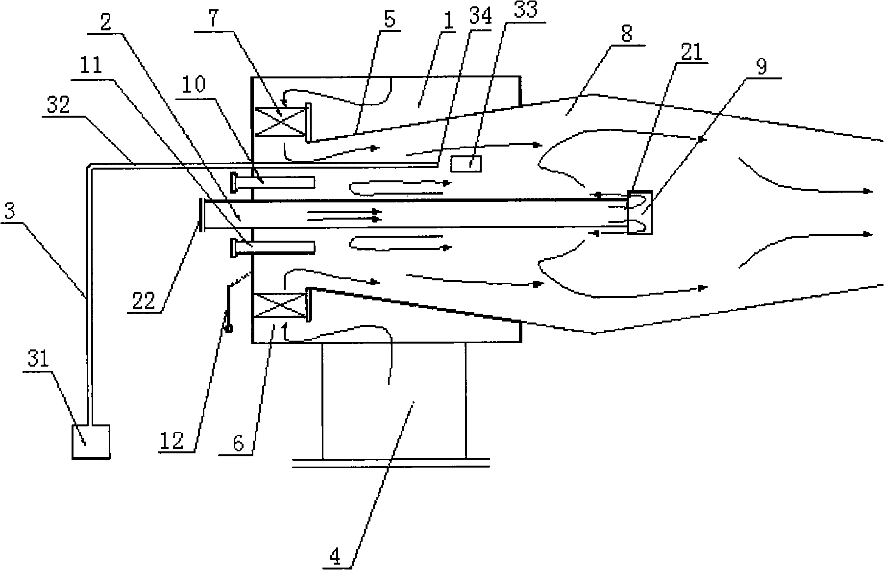
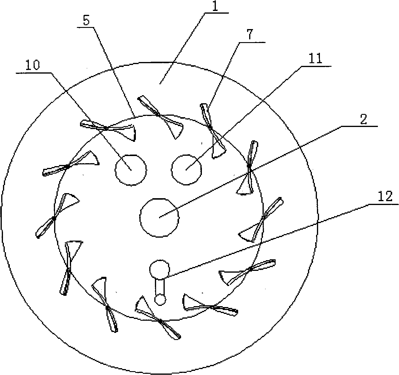
[0013] Such as figure 1 As shown, the present invention includes a bellows 1, a powder feeding pipe 2, an ignition device 3 and a blowing pipe 4. A cylindrical fixed baffle 5 with a conical cross-section is arranged axially inside the bellows 1, and an annular gap 6 is left between one end of the fixed baffle 5 and the bellows 1, and a plurality of swirl blades 7 are arranged in the circumferential direction of the annular gap 6. There is a pre-chamber 8 inside the fixed baffle 5 .

[0014] The outlet end 21 of the powder feeding pipe 2 runs through the center of the air box 1 and enters the pre-combustion chamber 8, the inlet end 22 is arranged outside the air box 1, and the powder feeding pipe 2 and the air box 1 are fixedly connected. A backflow cap 9 is disposed at the end of the outlet end 21 , and a certain gap remains between the backflow cap...


PUM


Abstract

The invention relates to a pulverized coal burner which is characterized by comprising an air box, a powder feeding pipe, an ignition device and a blast pipe; a cylindrical fixed baffle plate with a conical cross section is axially arranged in the air box, an annular gap is left between one end of the fixed baffle plate and the air box, and a plurality of swirl vanes are circumferentially arranged in the annular gap; a precombustion chamber is arranged inside the fixed baffle plate; the outlet end of the powder feeding pipe penetrates the center of the air box to enter in the precombustion chamber, the inlet end of the powder feeding pipe is arranged outside the air box and connected with a feeder device, and the powder feeding pipe is fixedly connected with the air box; a return flow cap is arranged at the tail end of the outlet end of the powder feeding pipe and a special gap is left between the return flow cap and the outlet end of the powder feeding pipe; the ignition device comprises a fuel tank, a conduct pipe and an ignition electrode, wherein the fuel tank is arranged outside the air box; one end of the conduct pipe is connected with the fuel tank and the other end of the conduct pipe penetrates the air box to enter in the precombustion chamber to form a spouting vent; the ignition electrode is arranged at one side adjacent to the spouting vent; and one end of the blast pipe is connected with the air box and the other end of the blast pipe is connected with an air blower. The invention can be widely used in various small and medium-sized industrial coal powder boilers.

Description

technical field [0001] The invention relates to a combustion device, in particular to a pulverized coal burner suitable for medium and small industrial pulverized coal boilers. Background technique [0002] At present, the existing small and medium-sized industrial pulverized coal boilers, such as bed-fired boilers, reciprocating boilers and chain boilers, generally use traditional combustion devices, and these combustion devices use lump coal as the main fuel, and are not suitable for burning coal. Powder use. Currently, the pulverized coal burners used in power plant boilers generally have a volume structure that is only suitable for use in power plant boilers with huge furnaces, and cannot be directly used in small and medium-sized industrial pulverized coal boilers. And the existing combustion device that is used for oil-fired gas-fired boiler can't be directly used in the small and medium-sized industrial pulverized coal boiler because the fuel of conveying is differen...

Claims


Application Information

Patent Timeline
Patent Type & Authority Applications(China)
IPC IPC(8): F23D1/02
Inventor 王乃继纪任山冀飞周建明何海军范玮肖翠微张帆
Owner CHINA COAL RES INST
Learn More