
Electromagnetic valve solenoid

A solenoid, solenoid valve technology, applied in the direction of electromagnets, electromagnets with armatures, circuits, etc., can solve the problems of troublesome and large installation work

Inactive Publication Date: 2003-03-26
SMC CORP
View PDF0 Cites 8 Cited by
  • Summary
  • Abstract
  • Description
  • Claims
  • Application Information

AI Technical Summary

Problems solved by technology

[0008] In the above-mentioned well-known example, since the concave portion 61b of the bottom cover 61 is engaged with the convex portion 58a of the movable iron core 58, the bottom cover 61 cannot be pulled out from the movable iron core 58. The front end side of the iron core 58 is inserted into the iron core while adding a force exceeding the resistance force generated by the above-mentioned convex portion 58a, so a large force is required, and the installation work is troublesome.

Method used


Image

  • Electromagnetic valve solenoid
  • Electromagnetic valve solenoid
  • Electromagnetic valve solenoid

Examples


Embodiment Construction

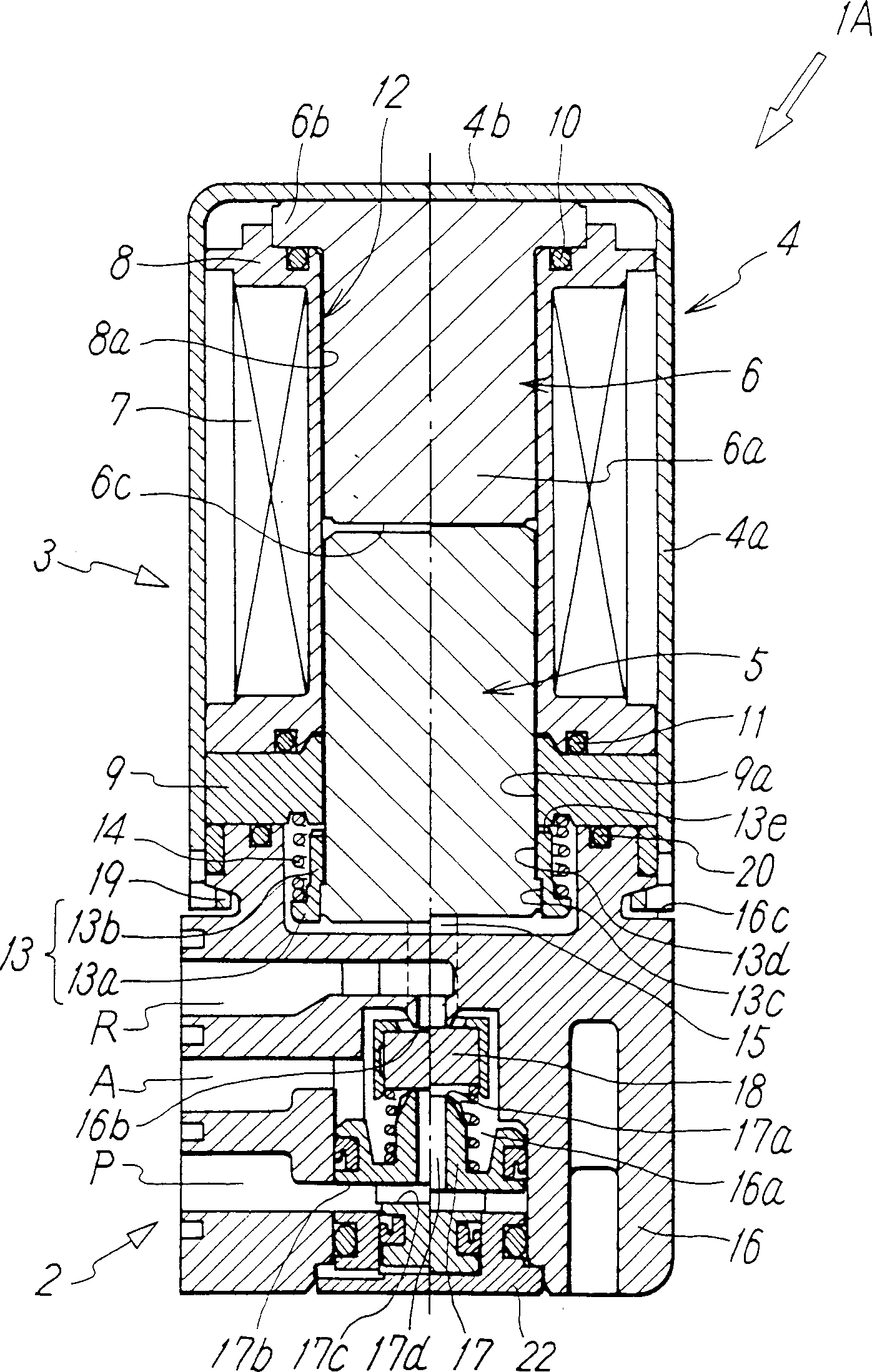
[0020] figure 1 The first embodiment of the present invention is shown, and a case where a solenoid valve solenoid is applied to a 3-port solenoid valve is shown. This solenoid valve 1A has a valve portion 2 in which a valve member 18 for switching a flow path is mounted, and the solenoid 3 that drives the valve member 18 .

[0021] The solenoid 3 includes a magnetic case 4 . The magnetic case 4 is composed of a cylindrical wall portion 4a having a substantially rectangular cross-sectional shape and an end wall portion 4b that closes one end side of the cylindrical wall portion 4a in the axial direction. The end of the valve skeleton 16 of the above-mentioned valve part 2 is fitted on the end of the opening.

[0022] Inside the above-mentioned magnetic case 4, a non-magnetic bobbin 8 having an oblong center hole 8a in the center and a coil 7 wound around the outer periphery is provided, and is connected in a state of being in contact with the end surface of the bobbin 8. Th...


PUM


Abstract

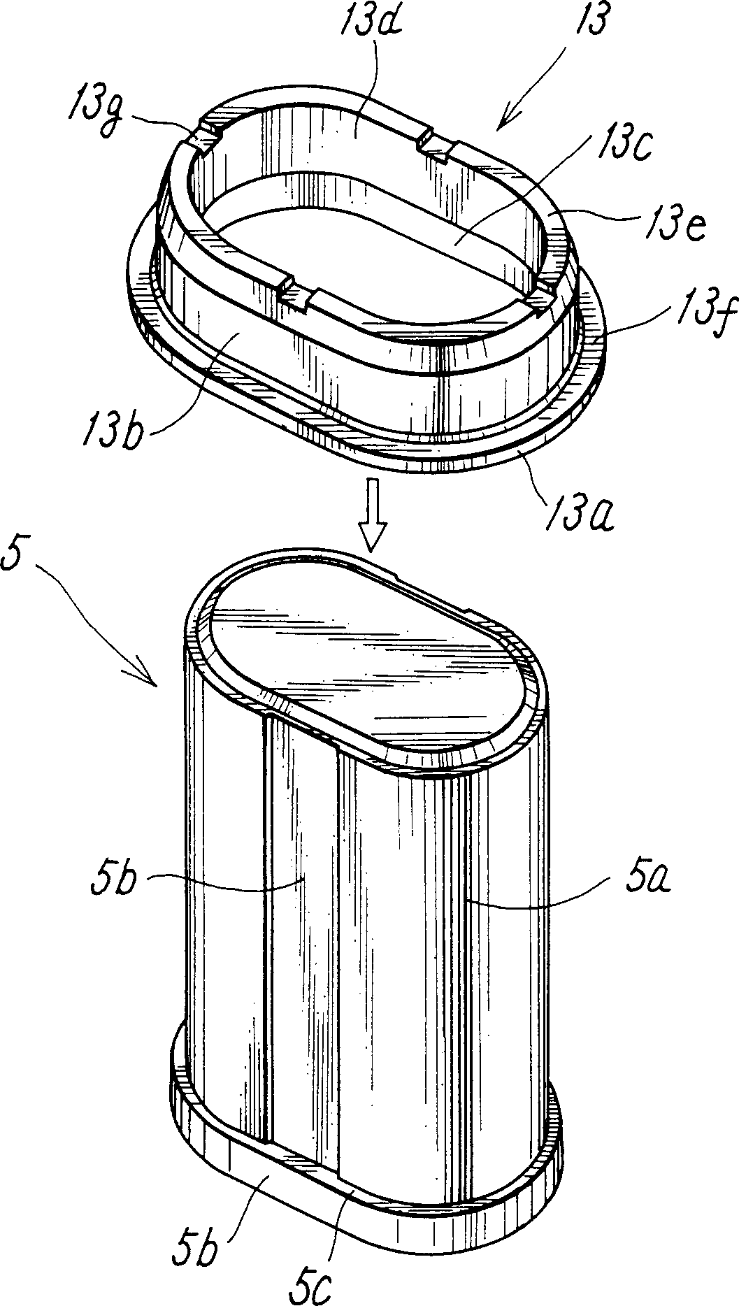
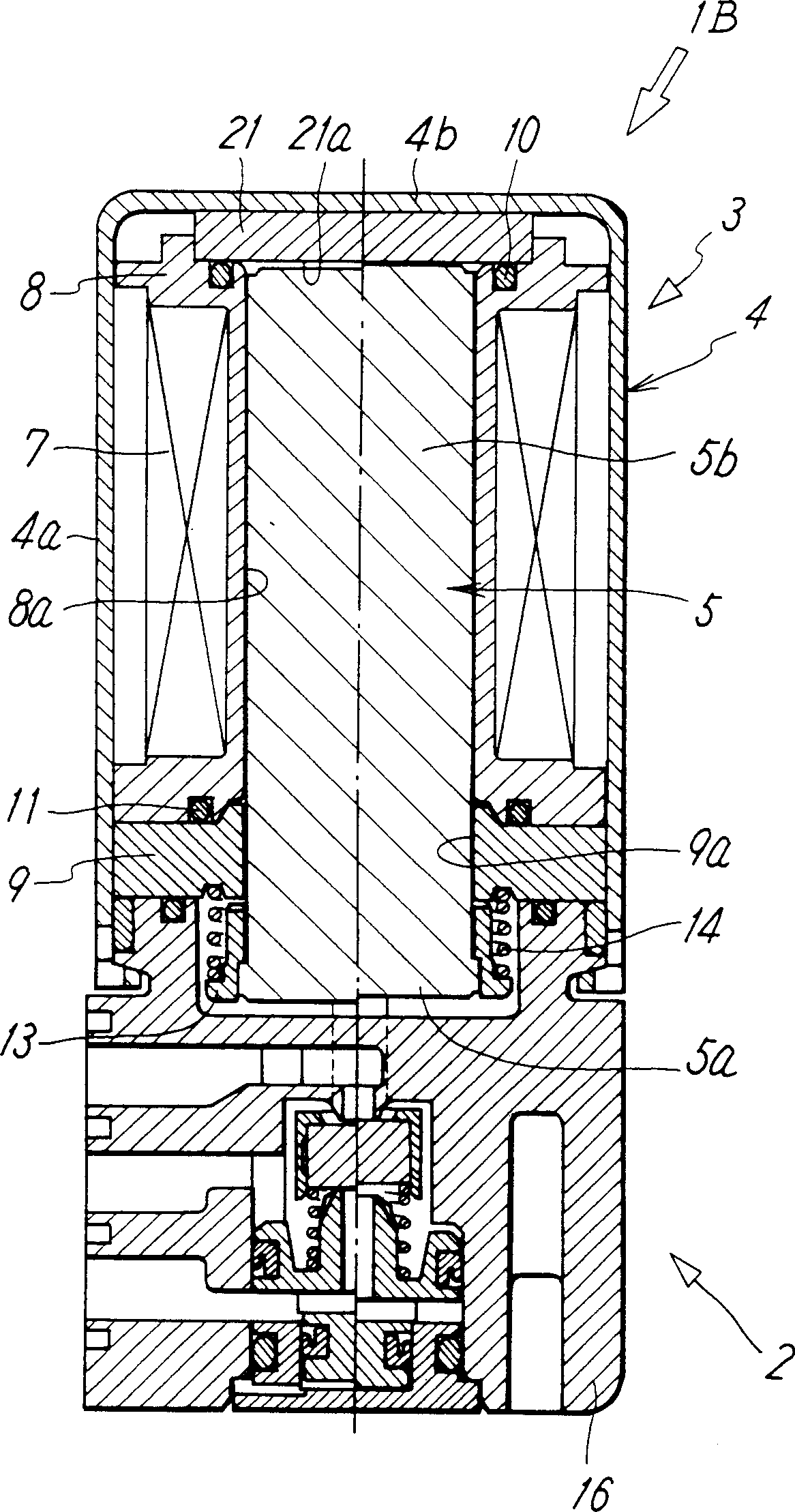
A solenoid for an electromagnetic valve is provided with a bobbin on which a coil has been wound, a movable iron core fitted into an iron core hole of the bobbin and a fixed magnetic pole member attracting the movable iron core, the movable iron core has a main body portion with an even section fitted into the iron core hole, and a flange portion with an even section formed on a portion extending from the iron core hole of the main body distal end, and the ring has a first portion which is positioned on a distal end side and which has a large diameter hole in which the flange portion is fitted and a second portion which is positioned on a proximal end side and which has a small diameter hole in which the main body portion is fitted.

Description

technical field [0001] The present invention relates to a solenoid for an electromagnetic valve that is mounted on an electromagnetic valve and drives a valve member for switching a flow path. Background technique [0002] The solenoid valve 50 previously proposed by the applicant is shown in FIG. The tube portion 52 is configured, and the valve member of the valve portion 51 is configured to be opened and closed by being pressed by the push rod 60 . [0003] The solenoid part 52 is configured such that a cylindrical magnetic case 53 having an opening for connecting the valve part 51 at one end is housed in a bobbin 55 around which a coil 54 is wound; The magnetic body plate 59; the fixed iron core 56 and the movable iron core 58 inserted in the central hole of the magnetic body plate 59 and the bobbin 55. [0004] The base end portion of the movable iron core 58 faces the fixed iron core 56 , and a bottom cover 61 serving as a stopper and a spring seat is fitted in the to...

Claims


Application Information

Patent Timeline
Patent Type & Authority Applications(China)
IPC IPC(8): F16K31/06H01F7/16H01F41/02
CPCF16K31/0624F16K31/0627F16K31/06
Inventor 佐藤秀治麻生佳男芳村亲一松本拓实
Owner SMC CORP
Learn More