Apparatus and method for automatically fetching static picture

A static image, automatic technology, applied in the direction of image communication, electrical components, etc., to achieve the effect of simplifying the operation process and shortening the processing time

Inactive Publication Date: 2003-03-26
UMAX DATA SYST
View PDF0 Cites 5 Cited by
  • Summary
  • Abstract
  • Description
  • Claims
  • Application Information

AI Technical Summary

Problems solved by technology

[0005] In addition, digital cameras, the darling of the times that can replace traditional cameras, are also a device that can be used to capture images, but they have a common disadvantage with traditional cameras, that is, for the images to be captured, the photographer himself is required to be pres

Method used


Image

  • Apparatus and method for automatically fetching static picture
  • Apparatus and method for automatically fetching static picture
  • Apparatus and method for automatically fetching static picture

Examples


Example Embodiment

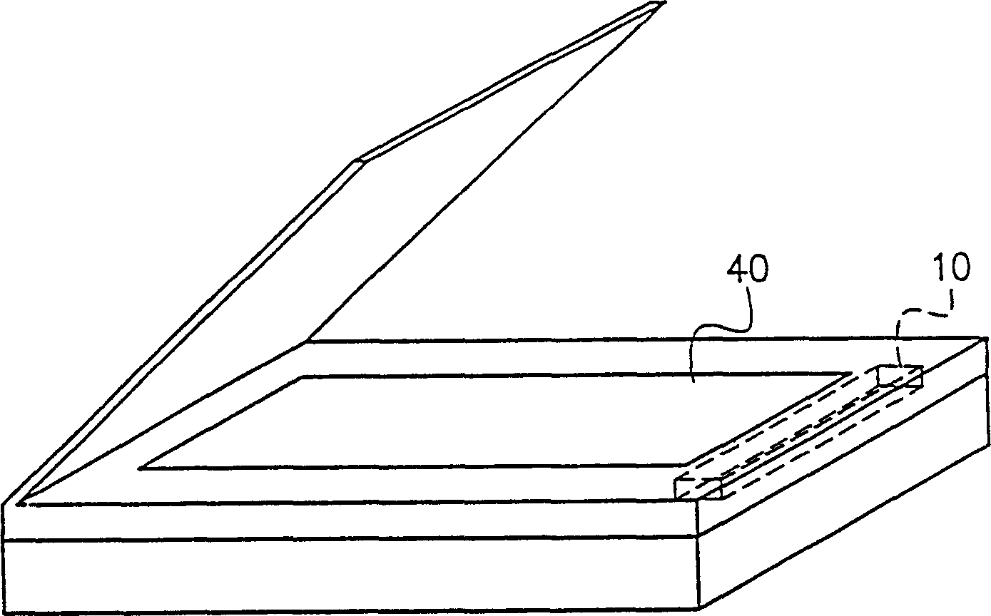
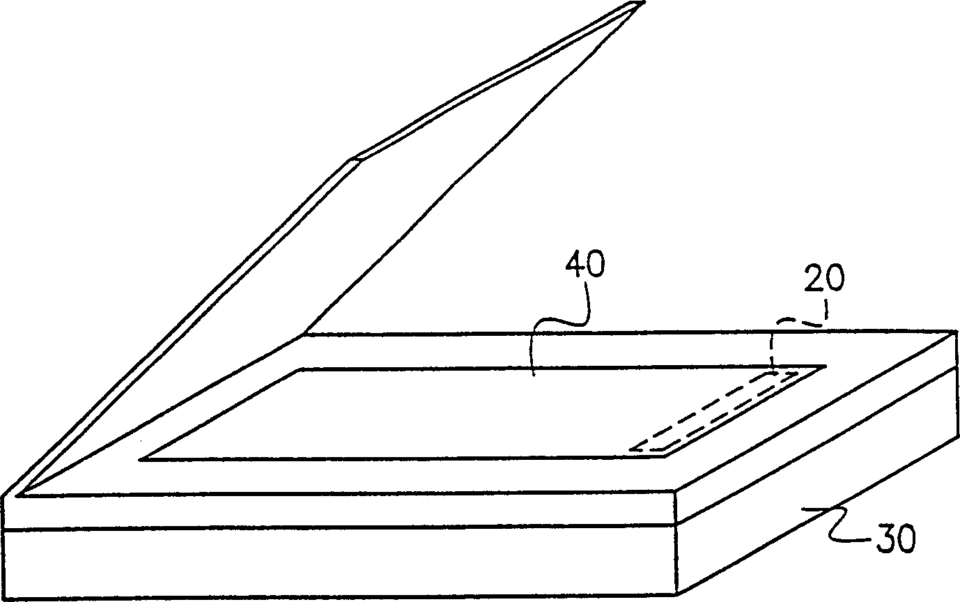
[0032] Please also refer to image 3 and Figure 4 This device is a flatbed scanner. In this flatbed scanner, there is a scanning platform 40 for placing static images of scanned documents.

[0033] The device for automatically capturing static images includes a scanning head 20 and a determining device 36.

[0034] Among them, the scanning head 20 is placed directly under the scanning platform 40 as a screen that continuously detects static images. That is to say, the scanning head 20 will be directly driven by the driving component (not shown) after the scanner is activated. The scanning platform 40 is directly below the beginning, so that after we open the upper cover of the scanner, the scanning head 20 can be seen directly above the scanning platform 40.

[0035] The judging device 36 is used to judge the difference between the image information detected by the scan head 20 in the previous period and the image information detected by the scan head 20 in the later period. Beca...


PUM


Abstract

The device for picking up the image automatically is the scanner. The method for picking up the image includes following steps. Whether the static image on the scanning platform is changed is detected. If the change of the static image on the scanning platform happens, then whether the change happened maintains a period of stable time but does not continute to change is determined. If yes, the preset action is executed.

Description

technical field [0001] The present invention relates to a device and method for continuously and automatically capturing still images, and in particular to a device and method for continuously detecting still images for subsequent image capture. Background technique [0002] In general offices or individuals who want to convert a document or image into an electronic document, they usually use a scanner to obtain the image, such as figure 1 The flatbed scanner in , and its use steps are as follows figure 2 As shown, in step S200, the user must first turn on the power of the scanner, and then in step S202, the user places the static image therein. [0003] But after step S200 turns on the power supply, the scanner must have a period of warm-up before it can start to operate, but during this time, the scanning head of the scanner is hidden in the rear, such as figure 1 As shown in the scanning head 10, after opening the upper cover of the scanner, looking down at the inside ...

Claims


Application Information

Patent Timeline
IPC IPC(8): H04N1/028H04N1/04
Inventor 郭士正余育侞
Owner UMAX DATA SYST
Why Eureka
Try Eureka