Ship structure for transporting oil and fresh water

A fresh water and hull technology, applied in transportation and packaging, hull, ship construction, etc., can solve the problems of fuel consumption and no benefit

Inactive Publication Date: 2003-04-02
约瑟夫·W·L·哈
View PDF0 Cites 17 Cited by
  • Summary
  • Abstract
  • Description
  • Claims
  • Application Information

AI Technical Summary

Problems solved by technology

Therefore, there is no benefit in the ret

Method used


Image

  • Ship structure for transporting oil and fresh water
  • Ship structure for transporting oil and fresh water
  • Ship structure for transporting oil and fresh water

Examples


Embodiment Construction

[0015] Next, an embodiment of the hull structure of a tanker for transporting oil and fresh water according to the present invention will be described with reference to the accompanying drawings.

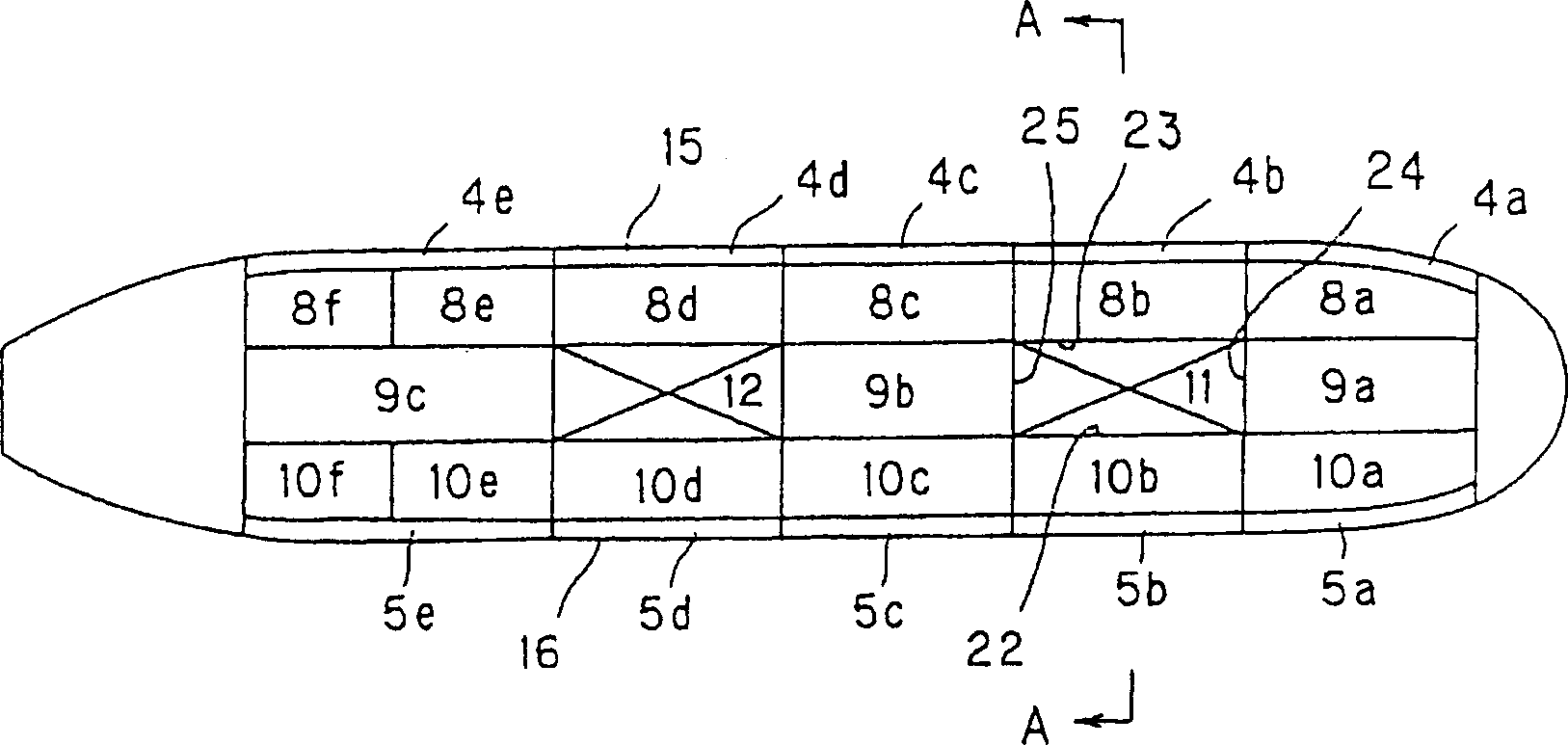
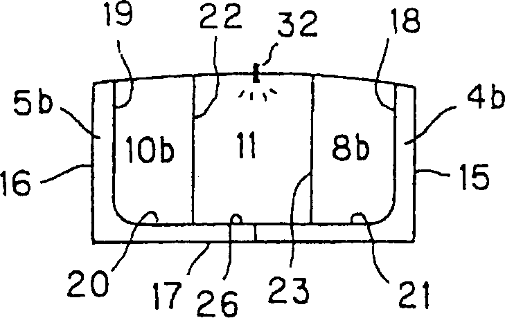
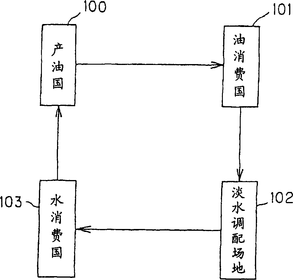
[0016] figure 1 It is a schematic plan view showing the hull structure of the double hull oil tanker of the present invention, figure 2 yes figure 1 The enlarged cross-section of line A-A, image 3 It's a nautical route map.

[0017] exist figure 1 with figure 2 Among them, from 4a to 4e are the fresh water cargo tanks on the port side, and from 5a to 5e are the fresh water cargo tanks on the starboard side. From 8a to 8f is the port oil cargo tank, from 9a to 9c is the central oil cargo tank, from 10a to 10f is the starboard oil cargo tank. 15, 16, 17 are hull shell plating, 18, 19 are longitudinal bulkheads, 20, 21, 26 are cabin inner bottom plates. Thus, the space of the entire double hull is constituted as fresh water cargo tanks from 4a to 4e and from 5a to 5e.

[...


PUM


Abstract

The invention provides a hull construction of a oil tank for transporting oil and fresh water by using all ballast tanks formed in a double hull space as fresh water tanks 4a-4e and 5a-5e, and two combining tanks 11, 12 are provided at a central portion of a hull for combining a sea water ballast tank and a fresh water cargo tank. In this manner, non-wasteful sailing of an oil tanker can be realized by utilizing the tanker for transporting oil cargoes on a forward route and fresh water on a backward route.

Description

technical field [0001] The present invention relates to a hull structure of a tanker for transporting oil and fresh water, in particular to a hull structure of a tanker for transporting oil and fresh water which can carry out voyage without waste because it can transport oil cargo on the forward journey and transport fresh water on the return journey. Background technique [0002] In recent years, in order to prevent oil outflow accidents on tankers, such as Figure 4 As shown, it is stipulated that double-layer sides and double-bottoms must be used as the ballast tanks 51, 52, that is, the structure of double hulls. In the oil tanker of this double hull structure, all the cabins are used as oil cargo tanks 53, 54, 55 except the cabins at the bow and stern. [0003] A general tanker arrives at an oil terminal in an oil-producing country such as an Arabian Gulf country with ballast seawater loaded into the ballast tanks 51 and 52 . Then, after the bal...

Claims


Application Information

Patent Timeline
IPC IPC(8): B63B11/04B63B3/20B63B13/00B63B25/08B63B25/12B63B35/00
CPCB08B9/08B63B3/20B63B3/62B63B11/04B63B25/12B63B43/06
Inventor 约瑟夫·W·L·哈
Owner 约瑟夫·W·L·哈
Why Eureka
Try Eureka