Rivet, riveted joint structure, riveting apparatus and riveting method

A riveting structure and rivet technology, applied in rivets, connecting components, screws, etc., can solve the problems of large driving force and low efficiency

Inactive Publication Date: 2003-04-16
TOYOTA JIDOSHA KK
View PDF1 Cites 19 Cited by
  • Summary
  • Abstract
  • Description
  • Claims
  • Application Information

AI Technical Summary

Problems solved by technology

In addition, due to these protrusions 306, the distal end 304A does not deform very quickly to the outside of the stem 304, and a large driving force is required for this.
Therefore, the efficiency of riveting the rivets in Figures 4 and 5 into the workpiece is very low

Method used


Image

  • Rivet, riveted joint structure, riveting apparatus and riveting method
  • Rivet, riveted joint structure, riveting apparatus and riveting method
  • Rivet, riveted joint structure, riveting apparatus and riveting method

Examples


Embodiment Construction

[0053] Below, refer to Figures 6A to 6C ,as well as Figure 7 A first embodiment of the first and second aspects of the present invention is described.

[0054] Such as Figure 7 As shown, the rivet 10 of this embodiment is a hollow rivet, which consists of a head 12 and a cylindrical portion 14 extending from the back of the head 12 . The head 12 of the rivet 10 has an inverted frusto-conical recess 20 in its substantially central portion. In addition, on the bottom 22A of the cylindrical portion 14 of the rivet 10 there is a conical protrusion 24 .

[0055] Next, a method of riveting or fastening using the rivet of this embodiment will be described. At first, as Figure 6A As shown, the distal end 14A of the cylindrical portion 14 of the rivet 10 is placed on one of the two plates 16 and 18 to be fastened (16).

[0056] Next, if Figure 6B As shown, a first punch 32 is used to press or hit the head 12 of the rivet 10, so that the die 34 arranged on this side of the pl...


PUM


Abstract

A rivet is provided which includes axially opposite end portions at least one of which is more likely to be deformed radially outwards than a remaining portion thereof, and the remaining portion is more resistant to a load applied in an axial direction of the rivet than the axially opposite end portions. As one example, the rivet (10) includes a head portion (12) and a cylindrical portion (14) that extends from the head portion (12), and a recess (20)is formed in the head portion (12) so as to be open to a top surface of the head portion.

Description

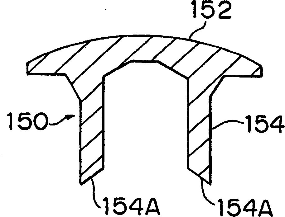
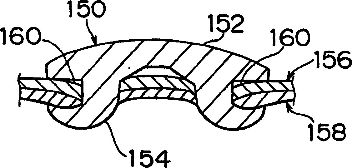
technical field [0001] The invention relates to a rivet, a riveting structure, a riveting device and a riveting method. More particularly, the present invention relates to rivets, riveting structures, riveting devices and riveting methods for automobile bodies and the like. Background technique [0002] Japanese published patent document Hei 8-4732 discloses a riveting structure and riveting method for an automobile body. [0003] As shown in FIG. 1, the rivet 150 used in this riveting structure is a hollow rivet consisting of a head 152 and a cylindrical portion 154 extending from the lower surface of the head 152. The distal end 154A of the cylindrical portion 154 forms an acute angle on its outer circumference such that the distal end 154A is conical from its outer edge toward its inner edge. Because of the shape of the distal end 154A, the rivet 150 can easily enter or penetrate a metal plate or plates with high efficiency. [0004] However, as shown in FIG. 2, in thi...

Claims


Application Information

Patent Timeline
Patent Type & Authority Applications(China)
IPC IPC(8): B21J15/02B21J15/10F16B5/04F16B19/06F16B19/08F16B19/10
CPCF16B5/04B21J15/025F16B19/083B21J15/10F16B19/086F16B19/06F16B19/1027Y10T29/49943F16B19/08
Inventor 井口博行佐野夏茂
Owner TOYOTA JIDOSHA KK
Why Eureka
Try Eureka