
Manhole cover

a manhole cover and manhole technology, applied in the field of manhole covers, can solve the problems of affecting the height of manhole covers, affecting the operation of manholes, and destroying height-adjusting materials such as bricks, and causing sinking downwards, etc., to achieve the effect of preventing variation of the height of the manhole cover, enhancing the strength of fixing, and enhancing the stability against external forces

Inactive Publication Date: 2013-09-24
LEE JAE DUK
View PDF15 Cites 7 Cited by
  • Summary
  • Abstract
  • Description
  • Claims
  • Application Information

AI Technical Summary

Benefits of technology

The present invention is about a device that prevents dirty water, rainwater, and other foreign matter from entering a manhole. It also improves fastening strength and stability against external force by using two or more spiral ribs to secure the upper and lower bodies. Catching rods prevent rotation of the upper body and maintain balance. The invention also enhances water sealing ability by using a pressing ring and a second groove to securely hold a packing member. Overall, the invention prevents damage to the manhole and improves its performance.

Problems solved by technology

However, since the existing manhole cover cannot be adjusted in its height, the height between slab of manhole structure and road surface is not constant for each manhole, and thus, in the installation of most manhole covers, in order to make the manhole cover flush with the road surface, a space between lower portion of the manhole cover and the slab of the manhole structure is filled with height-adjusting material such as bricks.
Therefore, there is a problem that the height-adjusting material such as bricks is destroyed and sinks downward due to reduction of strength of the bricks etc. resulting from ingress of rainwater etc. and fatigue load such as repeated impact load of the vehicle after completion of construction, and accordingly frequent repairing of the manhole cover on the road is required, which makes management of the manhole difficult.
However, in the case of forming a single spiral rib only, horizontal angle of the rib may not be made on a plane and a certain degree of taper is generated due to problems occurring in the processes of molding and releasing of castings, and thus there is a problem that a minute play may occur due to the taper in coupling of the upper and lower bodies.
Furthermore, when the bolts are to be fastened to the upper body in order to prevent the play in coupling of the upper and lower bodies, necessary bolt-fastening holes should be formed, however, since the height of the upper body should be adjusted to make it flush with the road surface, the bolt-fastening holes are difficult to form or should be formed in a great number in the process of manufacturing in factory.
Therefore, there are problems associated with the manufacturing or operations on site are cumbersome, and there is a problem that since the bolt-fastening holes are scattered rainwater may ingress into the bolt-fastening holes in the case of the manhole requiring the waterproof.
Furthermore, since the upper body is secured to the lower body by means of the spiral rib only, the play occurs between the upper and lower bodies, and since the bolts securing the upper body to the lower body are installed in such a way to be connected to the lower body through the inside of the upper body, user should install the bolts while inclining into the inside of the upper body in order to install the bolts, hence there is a problem that installation of the bolts is very inconvenient.
Furthermore, since only single spiral rib is formed, displacement by rotation is longer in adjustment of the height, hence there is a problem that waste of manpower, equipment and time occurs.
Furthermore, since waterproof of the manhole cover cannot be smoothly achieved, there is a problem that rainwater may ingress into the inside of the manhole through the manhole cover.

Method used


Image

  • Manhole cover
  • Manhole cover
  • Manhole cover

Examples


Embodiment Construction

Modes for Carrying Out the Invention

[0069]Hereinbelow, constructions and operations of examples of the present invention will be described in detail with reference to the attached drawings as follows. Furthermore, concrete description of related known functions or constructions will be omitted in the description of the present invention if it is believed to unnecessarily obscure the gist of the present invention.

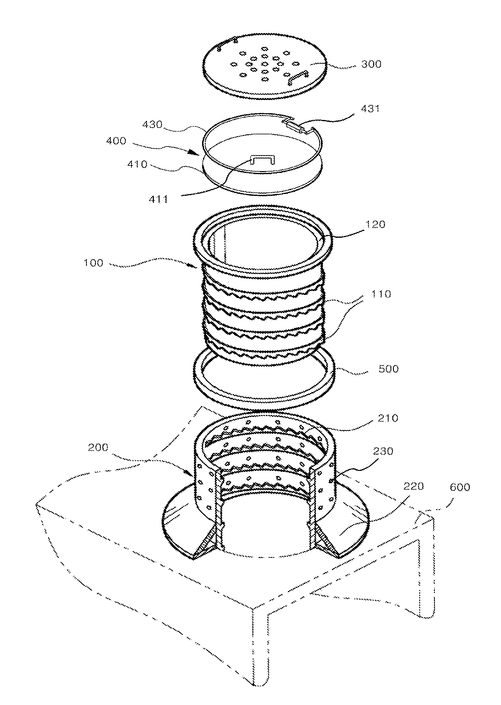
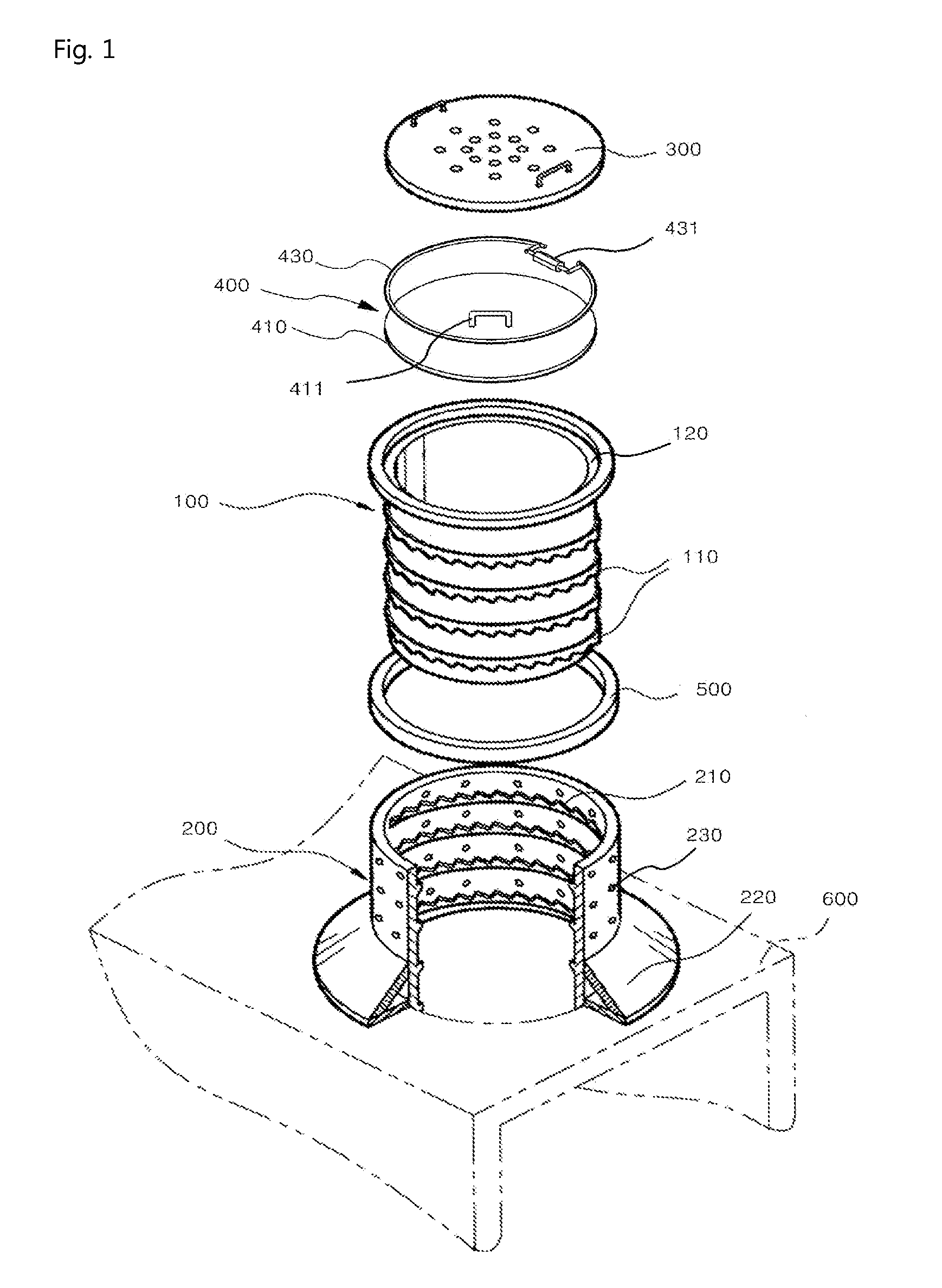
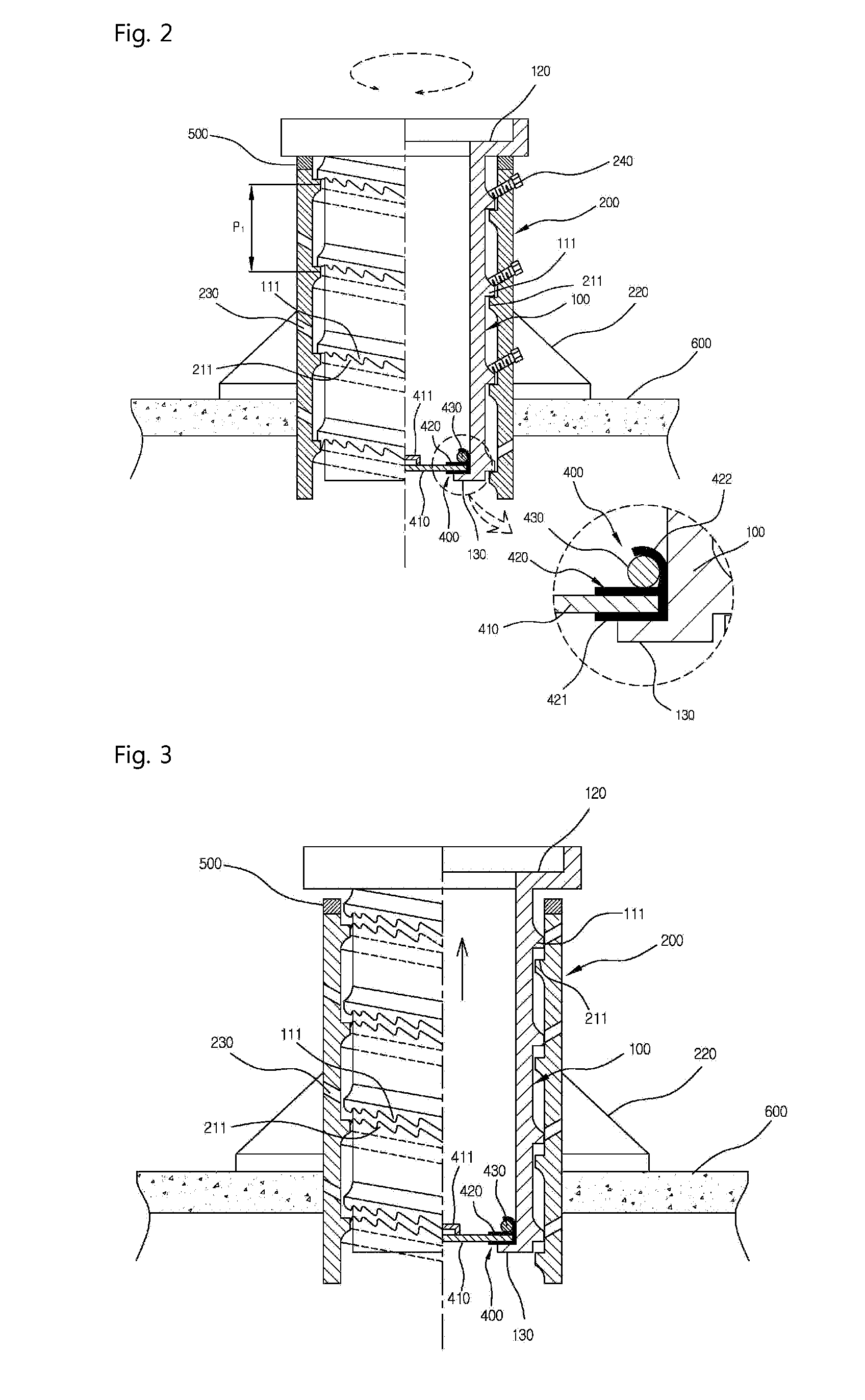
[0070]FIG. 1 is a perspective view illustrating a manhole cover of the present invention, FIG. 2 is a sectional view schematically illustrating a section of the manhole cover of the present invention, and FIG. 3 is a sectional view illustrating a state of operation for adjusting the height of the manhole cover of the present invention. The manhole cover of the present invention comprises a lower body (200), the inside of which is hollow, with a spiral rib (210) formed on the inner surface of the hollow space; an upper body (100) of tubular shape which is coupled inside the l...


PUM


Abstract

A manhole cover which has an upper body and a lower body coupled to each other to maintain balance, to endure loads applied from an external source in a stable manner, to protect the inside of the manhole from the ingress of rainwater, and to enable the upper body to be stably fixed inside the lower body.

Description

RELATED APPLICATIONS[0001]This application is a 371 application of International Application No. PCT / KR2009 / 007854, filed Dec. 29, 2009, which in turn claims priority from Korean Patent Application Nos. 10-2009-0005013, filed Jan. 21, 2009, and 10-2008-0137930, filed Dec. 31, 2008 each of which is incorporated herein by reference in its entirety.TECHNICAL FIELD[0002]The present invention relates to a manhole cover, more specifically, a manhole cover wherein ingress of rainwater and foreign matter is prevented by further comprising a waterproofing means arranged inside the upper body, and the upper and lower bodies are stably fastened to each other by forming two or more spiral ribs with the same pitch, and paly of the upper body is prevented by fastening the upper body to the lower body by bolts inclined downwardly, or inserting catching rods between the upper and lower bodies, and coupling strength is enhanced.BACKGROUND ART[0003]In general, the manhole is installed for maintenance...

Claims


Application Information

Patent Timeline
Patent Type & Authority Patents(United States)
IPC IPC(8): E02D29/12
CPCE02D29/14
Inventor LEE, JAE DUK
Owner LEE JAE DUK
Learn More