Fuel cell and fastening device for fuel cell

a technology of fuel cells and fastening devices, which is applied in the field of fuel cells, can solve problems such as the size increase of fuel cells, and achieve the effect of improving the strength of a structur

Active Publication Date: 2009-04-02
TOYOTA JIDOSHA KK
View PDF4 Cites 8 Cited by
  • Summary
  • Abstract
  • Description
  • Claims
  • Application Information

AI Technical Summary

Benefits of technology

[0004]It is an object of the invention to provide a fuel cell and a fastening device for the

Problems solved by technology

This gives rise to a problem of

Method used


Image

  • Fuel cell and fastening device for fuel cell
  • Fuel cell and fastening device for fuel cell
  • Fuel cell and fastening device for fuel cell

Examples


Embodiment Construction

[0025]To further make apparent the construction and operation of the foregoing invention, a fuel cell to which the invention is applied will be described below.

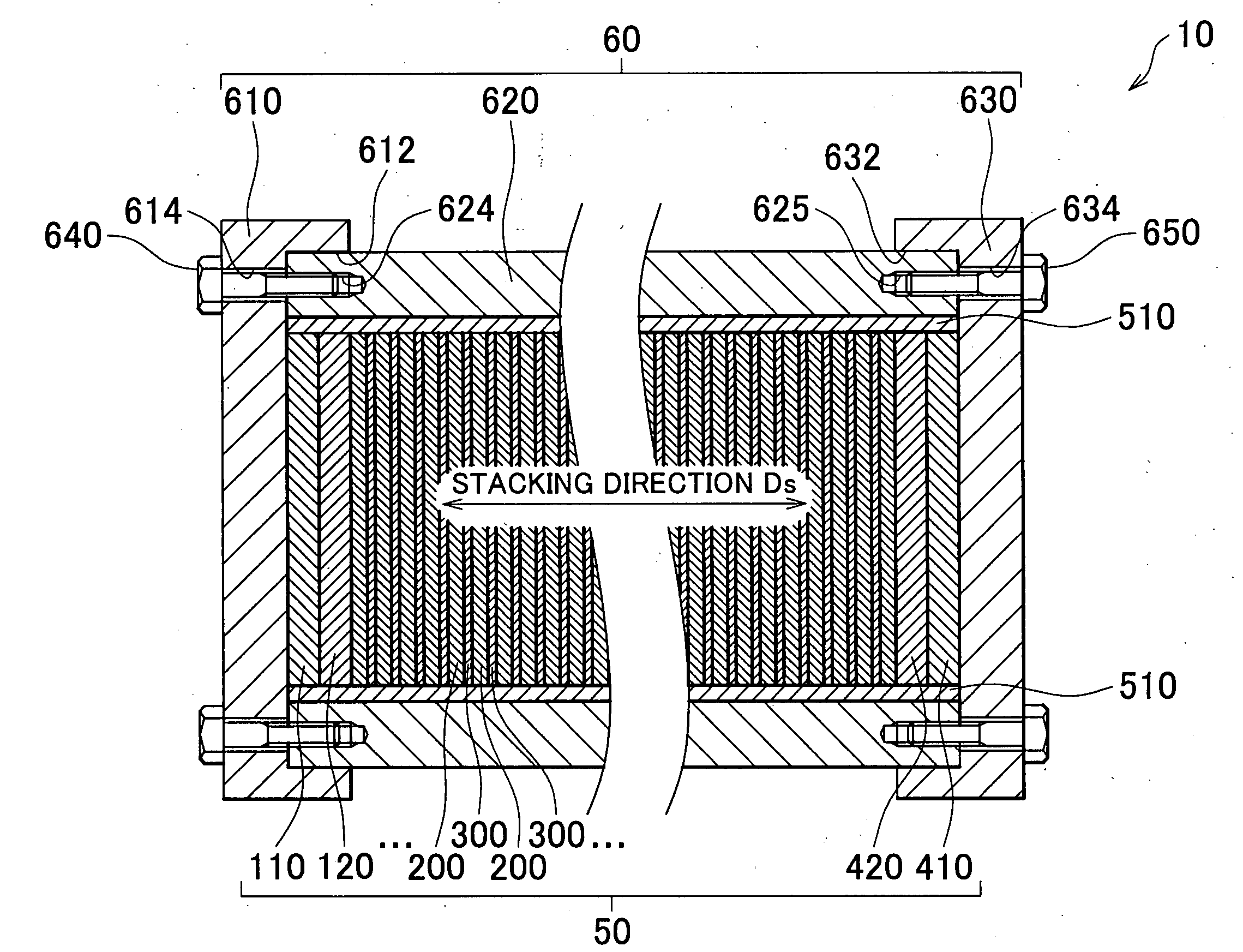
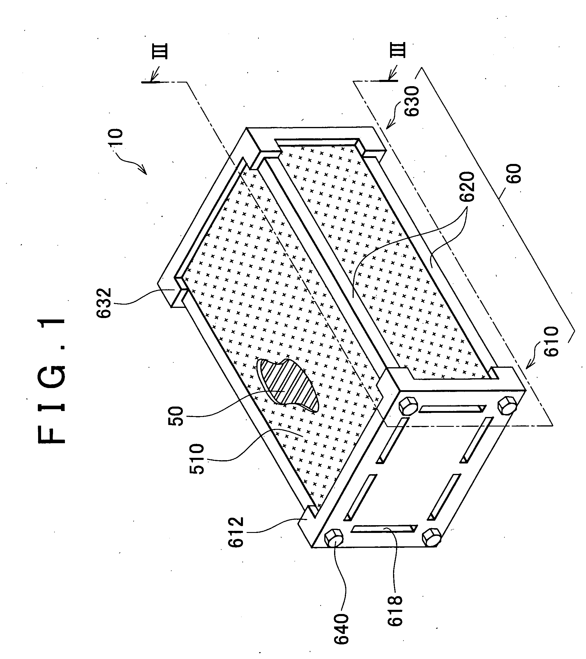
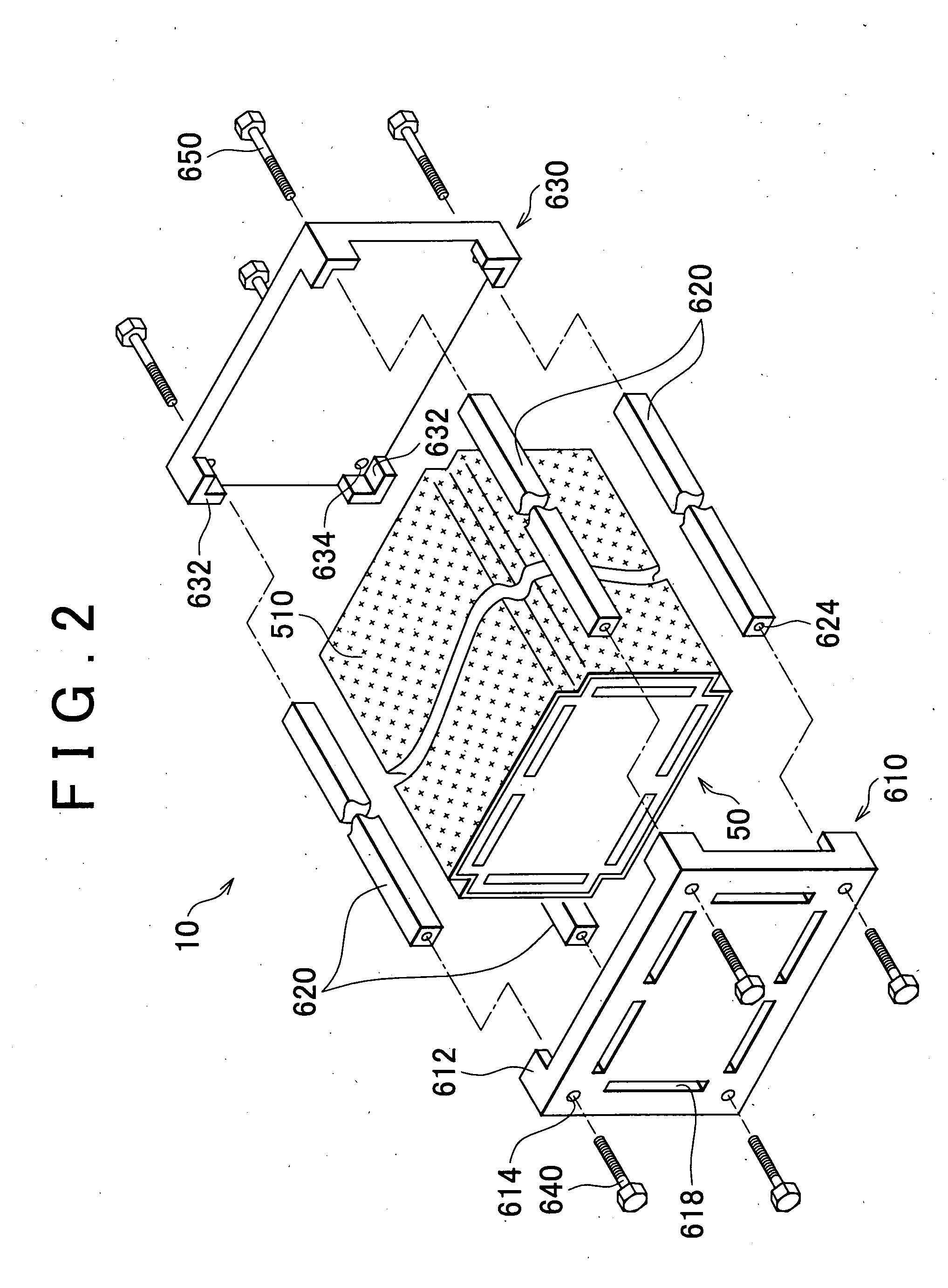
[0026]A-1. Construction of Fuel Cell 10: As shown in FIGS. 1, 2 and 3, the fuel cell 10 includes a cell stack 50 made up of a plurality of stacked unit cells, and a fastening device 60 that fastens the cell stack 50. The fuel cell 10 generates electric power through the electrochemical reactions of reactant gases supplied from outside the fuel cell 10. In this embodiment, the fuel cell 10 is a polymer electrolyte fuel cell, and the reactant gases used by the fuel cell 10 are a fuel gas containing hydrogen, and an oxidizing gas containing oxygen. The fuel gas used in the fuel cell 10 may also be a hydrogen gas stored in a hydrogen tank or a hydrogen storage alloy, or may also be a hydrogen gas obtained by reforming a hydrocarbon-based fuel. The oxidizing gas used in the fuel cell 10 may be, for example, air taken from the outs...


PUM


Abstract

A fuel cell includes: two end plates that sandwich a cell stack from both ends thereof in a stacking direction; a side member that defines a distance between the two end plates; a connecting bolt that connects the end plates and the side member by a bolt axial force acting substantially in the stacking direction; and a stopper portion that is provided in at least one of the end plates, and that contacts a surface of the side member that extends in the stacking direction and that is located substantially opposite from the cell stack.

Description

FIELD OF THE INVENTION[0001]The invention relates to a fuel cell that includes a cell stack made up of a plurality of stacked unit cells and that electrochemically generates electric power through the use of reactant gases. In particular, the invention relates to a structure in the fuel cell that fastens the cell stack.BACKGROUND OF THE INVENTION[0002]Japanese Patent Application Publication No. 2004-335336 (JP-A-2004-335336) discloses a fuel cell that has a structure for fastening a cell stack as described below. In this fuel cell, a pair of end plates that contact two opposite ends of a cell stack in the stacking direction, and a side member sandwiched between the two end plates are interconnected with a bolt axial force acting substantially in the stacking direction of the cell stack.[0003]In the foregoing fuel cell, the reaction or withstanding force needed to prevent relative displacement between the end plates and the side member due to load from a direction intersecting with t...

Claims


Application Information

Patent Timeline
IPC IPC(8): H01M2/02
CPCH01M8/0247Y02E60/50H01M8/248
Inventor OKABE, HIROKIHOTTA, YUTAKA
Owner TOYOTA JIDOSHA KK
Why Eureka
Try Eureka