Fastening bracket of deck cross member

a cross member and fastening technology, applied in the field of fastening brackets, can solve the problems of deformation of the fastening bracket, inability to adjust the position the bolt hole, and the gap between the fastening bracket and the fitting part, so as to reduce the danger of the bolt stripping of the fastening nut, and reduce the risk of bolt stripping

Inactive Publication Date: 2012-11-06
ASTEER
View PDF7 Cites 7 Cited by
  • Summary
  • Abstract
  • Description
  • Claims
  • Application Information

AI Technical Summary

Benefits of technology

[0013]Examples of the connection plate include (1) a connection plate structured of an intermediate plate provided with a deformation slit, and a pair of cross linking plates that connect the body plate with the intermediate plate and the surface contact plate with the intermediate plate, the cross linking plates having a width smaller than the intermediate plate. It is preferable that the cross linking plates for connecting the body plate with the intermediate plate and the surface contact plate with the intermediate plate be formed by elongating the demarcating slit to surround a periphery of the cross linking plates. The connection plate of the above-mentioned feature (1) adjusts a gap between the surface contact plate and the fitting part and a positional deviation between a fastening nut fixed to the surface contact plate and a bolt hole by elastically deforming or plastically deforming the intermediate plate.
[0015]Another example of the connection plate is (3) a connection plate structured of a deformation beam sandwiched between a body slit provided in the body plate and the demarcating slit, and a cross linking plate extending from the deformation beam and connected to the surface contact plate. It is preferable that the body slit be perpendicular to the connecting direction of the body plate and the surface contact plate connected by the connection plate, longer than the width of the cross linking plate, and shorter than the maximum outer shape width of the demarcating slit surrounding the connection plate. Accordingly, the deformation beam becomes longer than the cross linking plate, and shorter than the maximum outer shape width of the demarcating slit surrounding the connection plate, and the deformation beam can be fully elastically deformed or plastically deformed while restraining lowering of strength of the body plate. The connection plate of the above-mentioned feature (3) adjusts a gap between the connection plate and the fitting part and adjusts a positional deviation between the fastening nut fixed to the surface contact plate and the bolt hole by elastically deforming or plastically deforming the deformation beam.
[0016]The fastening bracket according to the invention adjusts a gap between the surface contact plate and the fitting part and adjusts a positional deviation between the fastening nut fixed to the surface contact plate and the bolt hole by elastically deforming or plastically deforming the cross linking plates structuring the connection plate, the intermediate plate sandwiched by the pair of cross linking plates, or the deformation beam extending from the cross linking plates. It is preferable that the surface contact plate be provided with a collar to be locked into a bolt hole provided at the fitting part of the vehicle body frame, in order that the surface contact plate can come close to the fitting part while keeping a parallel state for easy matching of the fastening nut and the bolt hole. The collar also functions as a member for guiding a bolt to be screwed into the fastening nut through the bolt hole.
[0018]The fastening bracket according to the invention adjusts a gap between the surface contact plate and the fitting part and a positional deviation between the fastening nut and the bolt hole through the elastic deformation or plastic deformation of the connection plate. This is a mechanism of the surface contact plate that is elastically deformed or plastically deformed in a direction close to or apart from the fitting part similarly to a conventional similar type of fastening bracket. In addition to the deformation in the above-mentioned direction, the connection plate according to the invention is bent in a planner direction parallel to the fitting part to be elastically deformed or plastically deformed. Furthermore, since the connection plate is elastically deformed or plastically deformed to the body plate and the surface contact plate, preventing the body plate and the surface contact plate from being elastically deformed or plastically deformed. Accordingly, the bracket according to the invention has an advantage in that residual stress is hardly generated in the body plate and the surface contact plate.
[0019]The collar has a function to cause the surface contact plate to come close to the fitting part while keeping a parallel state for easy matching of the fastening nut and the bolt hole. Furthermore, the collar has a function to guide a bolt to be screwed into the fastening nut through the bolt hole when the fastening bracket is fastened to the vehicle body frame. With the collar, the above-mentioned advantage (that only the connection plate is intensively deformed) becomes pronounced. Furthermore, a danger that the fastening nut is stripped by the bolt can be reduced by preventing inclination of the bolt to be screwed into the fastening nut. Since a fastening torque loss can be restrained when the bolt is being screwed, the assembly operation becomes simple. Furthermore, since it becomes possible that the surface contact plate is surface contacted with the fitting part without fail to fasten the fastening nut, sufficient fastening strength of the bolt can be ensured. Accordingly, the danger of loosening of the bolt due to vibration generated while traveling, for example, can be eliminated.

Problems solved by technology

However, a gap inevitably exists between the fastening bracket and the fitting part.
Furthermore, a positional deviation between the fastening nut and a bolt hole is inevitable.
There is a problem in that the fastening bracket is deformed and strength (mechanical strength) is lowered when the fastening bracket is bolted to the fitting part in such a condition.
However, a problem occurs that the number of parts and the number of steps are increased.
This results in insufficient elastic deformation or plastic deformation of the deformation anticipated part or the dimensional adjustment deforming section, and makes it impossible to eliminate a gap between the fastening bracket and the fitting part.
This may cause a male screw to strip a female screw of the fastening nut, resulting in a fastening torque loss.
In addition, sufficient fastening intensity of the bolt may not be secured, resulting in loosening of the bolt due to vibration generated while traveling, for example.

Method used


Image

  • Fastening bracket of deck cross member
  • Fastening bracket of deck cross member
  • Fastening bracket of deck cross member

Examples


Embodiment Construction

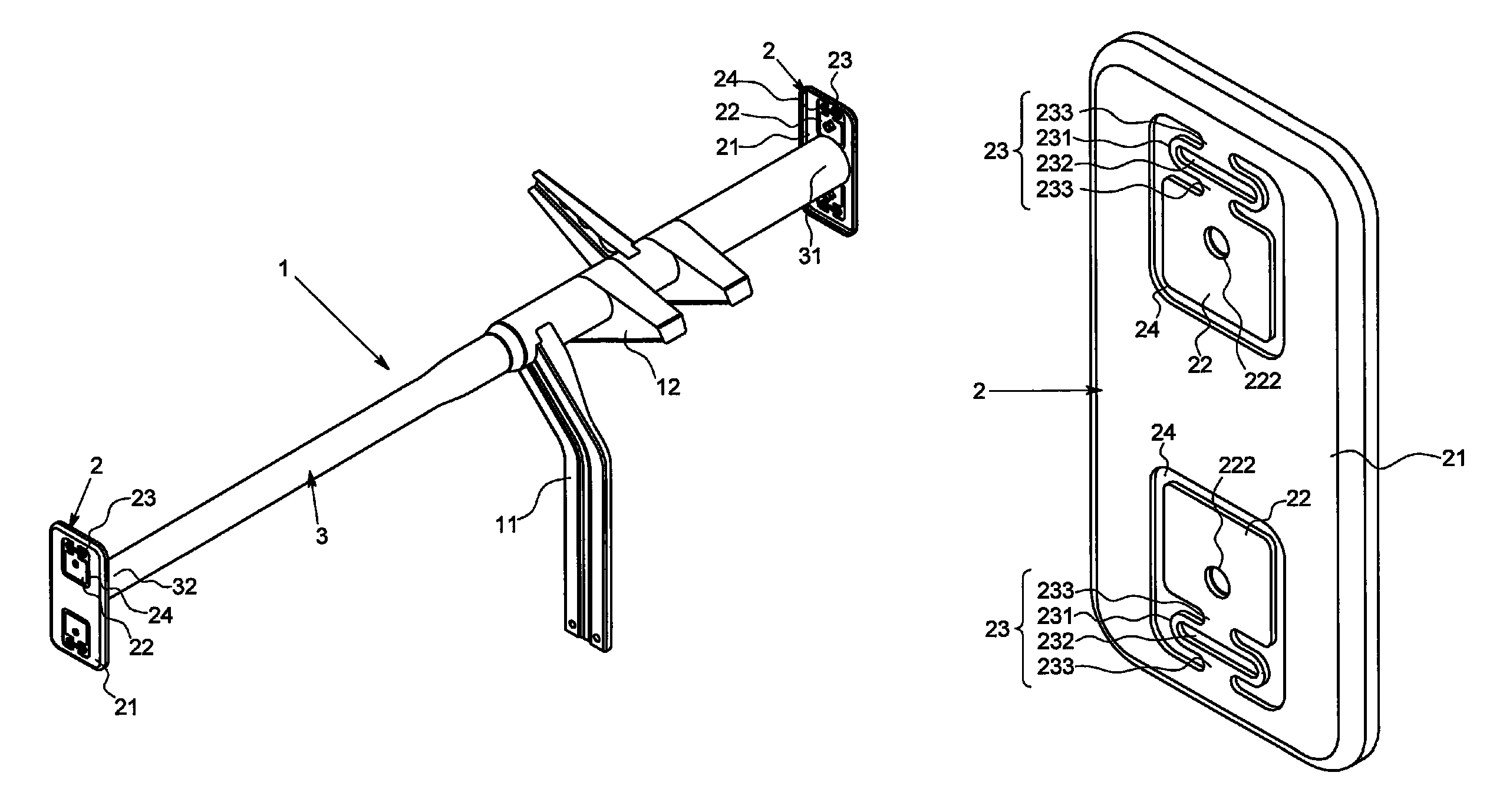
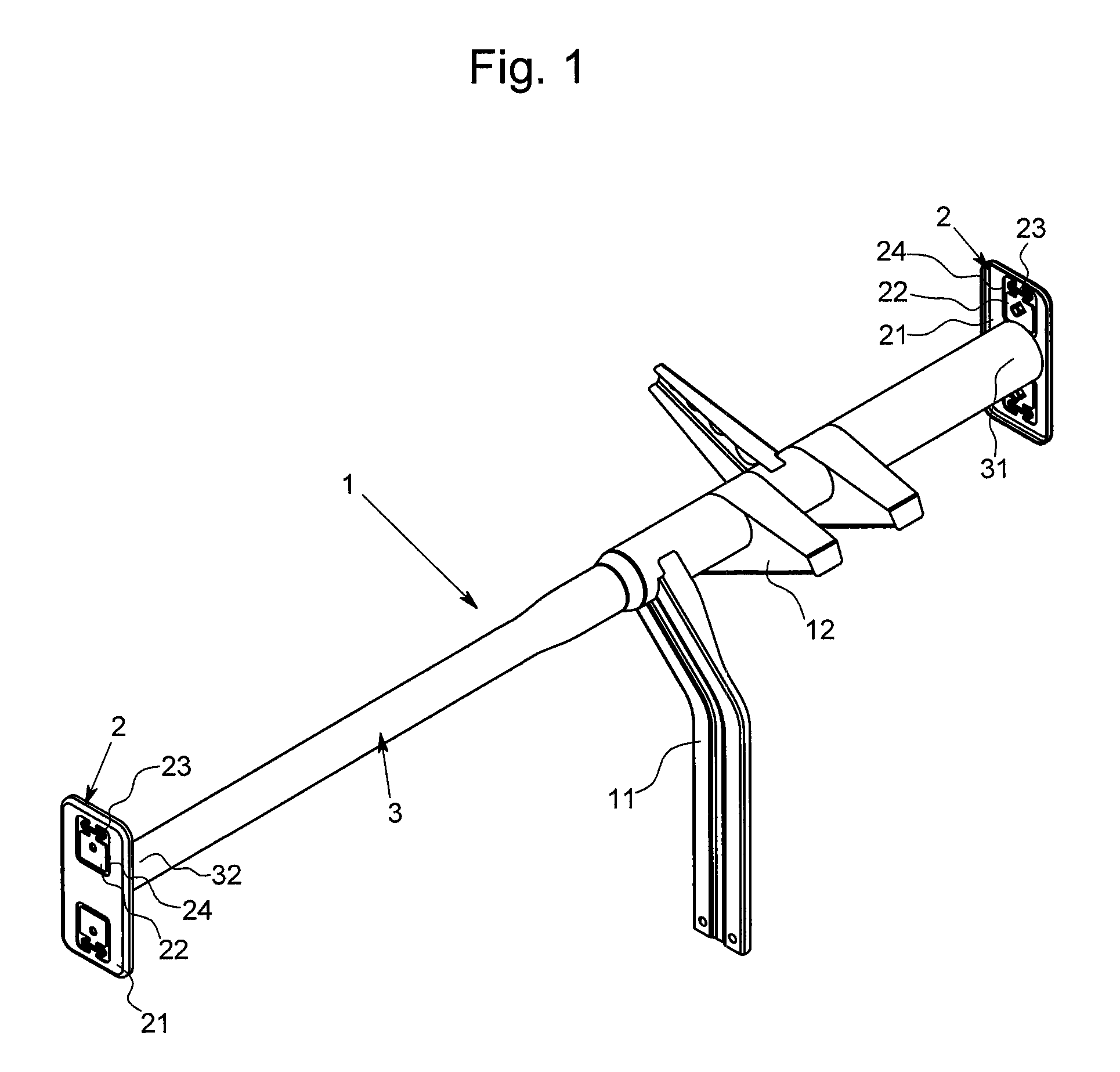
[0035]Hereinafter, an embodiment of the present invention will be described with reference to the accompanying drawings. As illustrated in FIG. 1, fastening brackets 2 according to the invention are joined to respective both ends of a deck cross member 3. The deck cross member 3 is fixed to a vehicle body frame 4 and used as a steering support frame 1. The fastening brackets 2 are joined to a driver seat side end 31 and a passenger seat side end 32 of the deck cross member 3 by welding. The deck cross member 3 in this example is basically a metal straight pipe having a circular cross section, and has different shapes on both ends with a larger diameter on the driver seat side and a smaller diameter on the passenger seat side. An intermediate stay 11 and a column bracket 12 are attached on the driver seat side having a larger diameter. The fastening brackets 2 on the driver seat and passenger seat sides have exactly the same specifications (that is, common to the right and left sides...


PUM


Abstract

The present invention provides a fastening bracket for fastening right and left ends of a deck cross member to respective fitting parts of a vehicle body frame. The fastening bracket includes a body plate to which one of the ends of the deck cross member is connected, a surface contact plate to which a fastening nut corresponding to a bolt to be inserted into corresponding one of the fitting parts of the vehicle body frame is fixed, the surface contact plate being provided in the body plate, a connection plate that is a part for connecting the body plate and the surface contact plate, the connection plate having a width in a direction perpendicular to a connecting direction of the body plate and the surface contact plate equal to or smaller than the surface contact plate, and a demarcating slit for demarcating the body plate and the surface contact plate.

Description

BACKGROUND OF THE INVENTION[0001]1. Field of the Invention[0002]The present invention relates to a fastening bracket for attaching a deck cross member structuring a steering support frame to a vehicle body frame.[0003]2. Description of the Related Art[0004]A steering support frame is structured of a deck cross member bridged between right and left vehicle frames. The deck cross member is fixed with bolting fastening brackets attached to respective right and left ends thereof with respect to fitting parts of the vehicle frames. In this context, there is no problem when a fastening bracket is surface contacted with the corresponding fitting part without a gap or a deviation therebetween. However, a gap inevitably exists between the fastening bracket and the fitting part. Furthermore, a positional deviation between the fastening nut and a bolt hole is inevitable. There is a problem in that the fastening bracket is deformed and strength (mechanical strength) is lowered when the fastenin...

Claims


Application Information

Patent Timeline
Patent Type & Authority Patents(United States)
IPC IPC(8): E04G25/00
CPCB62D25/147F16B5/025F16B37/061
Inventor WATANABE, DAISUKE
Owner ASTEER
Why Eureka
Try Eureka