Knotless suture anchoring devices and tools for implants

a technology of implanted tools and anchoring devices, which is applied in the field of implants for securing prosthetic implants, can solve the problems of increasing the difficulty of knotting, increasing the risk of tying knots, and devices being susceptible to changes in the magnitude of suture tension, so as to improve the ease of implantation, reduce surgical time and exposure, and be easy to install.

Active Publication Date: 2013-06-20
EDWARDS LIFESCIENCES CORP
View PDF15 Cites 80 Cited by
  • Summary
  • Abstract
  • Description
  • Claims
  • Application Information

AI Technical Summary

Benefits of technology

[0008]The present invention provides an improved suture locking device for securing heart valve repair or replacement prostheses in or near the heart. The apparatus and methods are particularly well suited for traditional surgery or minimally invasive surgery. The devices disclosed herein eliminate the need for surgical knots thus reducing surgical time and exposure. Further, the devices improve the ease of implantation because the clinician need not tie knots in the limited space in and around the heart. Finally, the suture locking devices are simple to install and their actuation does not affect suture tension.
[0012]A preferred system for locking a device onto at least one suture having a thickness, comprises an elongated delivery tool having a proximal end, a distal end, and a delivery tube therebetween having a lumen, the tool further including an elongated tension member that extends along the delivery tube. A suture locking device is positioned on the distal end of the delivery tool and has a bifurcated locking clamp including a pair of substantially similar clamp halves each having an exterior surface and an inner surface facing the inner surface of the other clamp half. The clamp halves are fixed axially with respect to one another but being connected for movement toward or away from one another to form a variable sized slot therebetween. The device further includes a biasing member that, in the absence of an object in the slot, urges the inner surfaces of the clamp halves together such that the slot has a width smaller than the suture thickness. A retention member positioned between the clamp halves against the force of the biasing member has a thickness that maintains the slot width large enough to permit passage of a suture therethrough. Removal of the retention member thus permits the biasing member to urge the inner surfaces of the clamp halves together and clamp the suture(s) therebetween. Wherein a distal end of the elongated tension member engages the retention member to enable tension in the tension member to apply a proximal force to the retention member. Finally, an actuator on the proximal end of the delivery tool causes relative axial displacement between the retention member and the suture locking device so as to remove the retention member from within the variable sized slot and permit the clamp halves to clamp the suture therebetween.
[0015]Alternatively, the biasing member comprises a coil spring, and the exterior surface of the clamp halves is at least partly cylindrical such that the coil spring provides a substantially uniform inward radial compressive force on the device. The system may further include a suture snare that passes from the proximal end to the distal end of the delivery tool and having a capture loop on a distal end. The capture loop extends from the lumen of the delivery tube through the variable sized slot of the suture locking device and is compressible to enable it to be pulled proximally through the slot. Another possibility is a tensioning assembly affixed to the proximal end of the delivery tool having an anchor for temporarily securing a suture that extends through the delivery tool and through the suture locking device. The tensioning assembly thus enables adjustment of the tension in the suture when secured to an implant location beyond the distal end of the delivery tool and suture locking device.
[0020]d. displacing the elongated tension member, proximally pulling the retention member from between the clamp halves, thus enabling the biasing member to force the clamp halves toward each suture and clamp the free ends therebetween.

Problems solved by technology

Forming knots in suture during open surgery is a simple matter, though time-consuming, but forming knots in sutures during endoscopic surgery can require two surgeons to cooperate in a multi-step process which is performed with multiple instruments to pass the needle and suture back and forth to tie the suture knot.
This is a cumbersome process that benefits from a clinician of great dexterity and patience.
In a minimally invasive surgery the clinician must use tools that can be passed through a small incision, thus making the tying of knots even more difficult.
Some of these devices are susceptible to changes in the magnitude of tension in the suture as they are being locked, either loosening or tightening the suture, while others may work loose if there is no additional mechanism to hold them in place.
Some devices such as U.S. Pat. No. 7,862,584 utilize a clamping system having a tortuous path for the suture, which are difficult to thread and also may work loose.

Method used


Image

  • Knotless suture anchoring devices and tools for implants
  • Knotless suture anchoring devices and tools for implants
  • Knotless suture anchoring devices and tools for implants

Examples


Embodiment Construction

[0056]Various suture locking devices of the present invention comprise heart valve repair or replacement prosthesis anchors that improve ease of implantation, reduce surgical exposure, and improve prosthesis attachment. It should be appreciated that the principles and aspects of the embodiments disclosed and discussed are also applicable to other types of surgical procedures, namely annuloplasty ring implant for heart valve repair. Furthermore, certain embodiments may also be used in conjunction with other medical devices or other procedures not explicitly disclosed. However, the manner of adapting the embodiments described to various other devices and functionalities will become apparent to those of skill in the art in view of the description that follows.

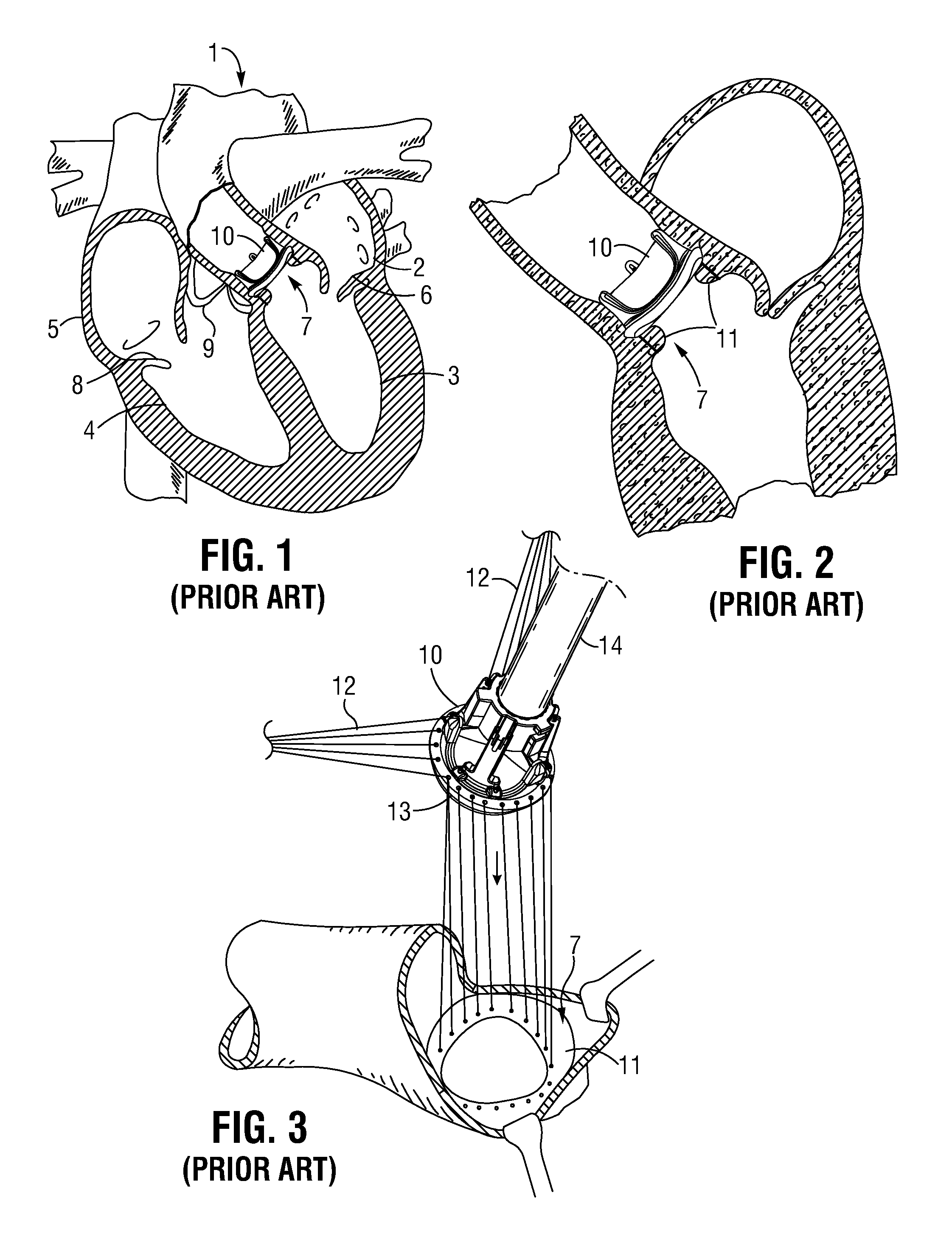
[0057]A schematic drawing of a surgical prosthetic heart valve implanted in the heart 1 by traditional methods is shown in FIG. 1. The left atrium 2 and the left ventricle 3 are shown separated by the mitral valve 6. The aortic va...


PUM


Abstract

Devices for securing prostheses such as heart valves or annuloplasty rings with sutures and without using knots are disclosed. The devices are particularly well suited for traditional surgery or minimally invasive surgery, and improve the ease of implantation by eliminating surgical knots a clinician would normally tie in the limited space in and around the implant site. The devices have opposed the clamp halves surrounded by a coil spring. Sutures pass between the clamp halves and the coil spring has an inner coil diameter sufficient to compress the sutures between the clamp. A retention member positioned between the clamp halves maintains a minimum space and therebetween to enable the locking device to be slid along the sutures into position, and to adjust the tension of the sutures therethrough. A delivery tool may be used to deliver and deploy the locking devices.

Description

RELATED APPLICATIONS[0001]The present application claims priority to U.S. Provisional Application Ser. No. 61 / 639,759, filed Apr. 27, 2012, and 61 / 577,255, filed Dec. 19, 2011.FIELD OF THE INVENTION[0002]The present invention relates to devices for securing prosthetic implants to soft tissue and, more particularly, to devices and methods for anchoring prostheses inside or near the heart using sutures without knots.BACKGROUND OF THE INVENTION[0003]Sutures are used for a variety of surgical purposes, such as approximation of tissue and ligation of tissue. When placing sutures, the strand of suture material to be used typically has a needle affixed to one end which is passed (looped) through the tissue to be approximated or ligated, forming a stitch. The stitch is then tensioned appropriately, and the two free ends of the suture loop, the needle end and the non-needle end, are knotted to retain the desired tension in the stitch. Forming knots in suture during open surgery is a simple m...

Claims


Application Information

Patent Timeline
Patent Type & Authority Applications(United States)
IPC IPC(8): A61B17/04
CPCA61B17/0401A61B2017/0488A61B17/0487A61B17/0469A61F2/2466A61F2/2412A61B17/0483A61B2017/0496A61F2/2427
Inventor CONKLIN, BRIAN S.CAMPBELL, LOUIS A.MARQUEZ, SALVADOR
Owner EDWARDS LIFESCIENCES CORP
Why Eureka
Try Eureka