Intravascular hinge stent

a hinge stent and stent technology, applied in the field of expandable endoprosthesis, can solve the problems of permanent deformation of the stent, inability to support or balance the radial force, and irreversible crushing of the stent, and achieve the effects of reducing the width, increasing the axial flexibility, and reducing the risk of fractur

Inactive Publication Date: 2012-03-15
DRASLER WILLIAM JOSEPH +1
View PDF2 Cites 80 Cited by
  • Summary
  • Abstract
  • Description
  • Claims
  • Application Information

AI Technical Summary

Benefits of technology

[0028]The stent of the present invention allows a balloon-expandable and noncrushable stent to be formed from a metal that has a relatively high yield strength or high expansion yield force. The yield strength for the metal of the stent can be high enough such that when the stent is formed into an oval or flattened shape such as that found during crush deformation, the struts do not surpass their elastic limit and hence remain elastic. Each strut can be connected to two nodes through a hinge. The hinge is configured to provide plastic expansion deformation to the stent as it extends from a nondeployed insertion diameter to a deployed implantation diameter. The expansion deformation is focused in the hinge region such that localized plastic deformation occurs in the hinge. The hinge resists bending in the radial direction such as that deformation produced during a crush deformation. The result is a stent with appropriate inserted stent compression yield force that can be properly overcome by the balloon expansion applied force from the balloon dilitation catheter and strength to support the blood vessel and resist vessel contraction, and further provide the stent with non-crush characteristics.
[0029]A balloon-expandable stent of one embodiment of the present invention can be modified to provide modified stent expansion and compression yield force characteristics or modified implanted stent crush yield force characteristics independent of one another. This is accomplished by altering a radial dimension for the hinge and changing its width and length perpendicular to the radial dimension. For example, to increase the implanted stent crush yield force while maintaining the inserted stent compression yield force constant, the struts can be first enlarged in their sectional area to provide the desired crush yield force, or the material of the stent can be changed to attain a higher yield strength material. The struts can be formed of appropriate material and thickness to ensure that they remain elastic for any reasonable crush deformation encountered during normal use. The radial dimension of the hinge can be increased to provide an accompanying similar increase in crush yield force to the node. The width of the hinge in a direction perpendicular to the radial dimension and lying in the uniformly curved surface of the stent can be decreased such that the inserted stent compression yield force will remain constant. The hinge length can be decreased to further focus the expansion deformation in the hinge and ensure that plastic deformation will occur in consideration of the narrowing of the hinge width. If the hinge length is maintained in a longer configuration, the hinge can be configured to remain in an elastic state and not undergo a plastic deformation during expansion deformation; this node and hinge design of the present stent thus allows the formation of a self-expandable stent to also be accommodated.
[0032]The stent of the present invention allows a self-expandable stent to be formed out of an elastic metal that will not plastically deform during normal use involving elastic expansion deformation or during exposure to a crush deformation. The struts could be formed with a sectional dimension that provides the self-expandable stent with an elastic crush deformation when exposed to an external tissue crush applied force to form an oval shape due to a crush deformation. The implanted stent crush elastic force of the stent can be high or low depending upon the desired properties of the stent. The struts are connected to one or more nodes through a hinge. The hinge has a greater radial dimension than the struts to resist the formation of an oval cross section associated with crush deformation. The hinge has a width that can be adjusted to provide an implanted stent expansion elastic force that is appropriate to resist the tissue compression applied force of the blood vessel. The hinge length can further be adjusted to alter the implanted stent expansion elastic force. The result is a self-expandable stent with appropriate expansion elastic force properties and a soft feel in a crush deformation. Similarly, the stent can have appropriate or nominal expansion elastic force properties and a very rigid, difficult to crush characteristic associated with a large implanted stent crush elastic force.
[0033]A self-expandable stent of the present invention can be modified to alter the inserted stent and the implanted stent expansion elastic force or implanted stent crush elastic force independent of one another. For example, to increase the crush elastic force while maintaining the inserted or implanted expansion elastic force, the struts can be enlarged in sectional area to provide the desired crush elastic force. The radial dimension of the hinge can be increased to provide an accompanying similar increase in crush elastic force in the node region. The width of the hinge in the uniformly curved surface of the stent can be decreased such that the expansion elastic force will remain constant. The hinge length can be decreased to provide a more focused bending of the hinge through a smaller radius of curvature to generate the appropriate expansion elastic force.
[0038]In still another embodiment the stent is formed in an array of nodes and struts wherein each node is connected to three struts. The configuration of nodes and struts can be used for either a balloon-expandable stent or a self-expandable stent. The presence of hinges with a greater radial dimension and a smaller width that the struts provides this embodiment with the advantage of decoupling the inserted stent compression yield force and the implanted stent expansion yield force from the implanted stent crush yield force, and decoupling the implanted and inserted stent expansion elastic force from the implanted stent crush elastic force. In addition, axial flexibility can be provided directly from the array of nodes and struts without the need for connecting means.
[0039]In one more embodiment of the present invention the metal tube can be formed into a stent with an array of nodes and struts that have each node connected to two struts. The node can be a single hinge that connects two struts. The hinges and struts can be formed in any combination of straight or curved shape along with any combination of axial, circumferential, or oblique orientation for either the hinges or struts. This stent can be formed into a balloon-expandable stent or a self-expandable stent. In a balloon-expandable stent the hinge uncouples the inserted stent compression yield force and the implanted stent expansion yield force from the implanted stent crush yield force. The strut portion is constructed such that crush deformation will not result in plastic deformation; the strut will remain elastic. This allows the balloon-expandable stent to be balloon-expandable and noncrushable. In a self-expandable stent the hinge uncouples the inserted and implanted stent expansion elastic force from the implanted stent crush elastic force. The strut portion is similarly constructed such that crush deformation will not result in plastic deformation of the strut which will remain elastic. This allows the self-expandable stent to have independent design of inserted and implanted stent expansion elastic force with respect to implanted stent crush elastic force.

Problems solved by technology

Advantages of the balloon expandable stents lies in part in the ability of these stents to be delivered accurately to the site of a stenotic lesion.
Some difficulties associated with balloon expandable stents can be related to their lack of flexibility and their inability to withstand external forces that can lead to irreversible crushing of the stent.
Other stents have a structure that is made more flexible but are not appropriately capable of supporting or balancing the radial forces applied by the vessel acting to compress the stent.
Arteries of the neck and leg region can sometimes be exposed to such external forces resulting in permanent deformation of the stent and loss of vessel patency.
In the balloon expandable stents currently found in the prior art one cannot adjust the amount of force required to expand the stent independently from the force required to crush the stent.
As a result, a stent design that resists crushing action will generally be too stiff and require too much force to accomplish its deployment.
Some problems associated with self-expandable stents include the inability of the physician delivering the stent to define precisely the location of both ends of the stent.
Such length changes can result in inaccuracies in defining a precise placement for the stent.
This disadvantage can be somewhat offset by the ability of some self-expandable stents to resist crushing deformation associated with an external force directed toward the side of the stent.
Self-expandable stents also do not generally allow the radial expansion force to be adjusted independently from the stent forces that are directed to resist crushing forces.
The junction of the elongate member with the bar cannot be adjusted to resist crushing deformation without also affecting the force required to expand the stent from its nondeployed state to its deployed state; additionally, the compression balancing force would also be affected.
Although the connector members provide an enhanced axial flexibility, this stent is still subject to crush deformation.
If this stent were designed to expand upon exposure to a dilitation balloon with a nominal expansion applied force, it would not be able to resist crushing deformation when exposed to an external side force that can be encountered in a carotid or femoral artery position.
One cannot adjust the crush yield strength of this stent independently of the expansion yield strength.
These stents would be susceptible to irreversible crush deformation if exposed to an external force to the side of the stent.
This stent is not well suited to provide independent adjustment of compression yield force with respect to crush yield force.
As a result, this stent can be subject to crushing deformation even though the expansion and compression yield force are appropriate for allowing balloon expansion and support of the blood vessel.
Exposure of any of these stents to an external side force could lead to a crush deformation.
It is not possible for any of these stents to enhance the crush yield force without altering the expansion or compression yield force of the stent.
The latching or ratcheting mechanism adds to the size and the complexity of the device.
The stents disclosed by Wallsten are not well suited to independent adjustment of the crush and the expansion elastic balancing force.
Such stents with appropriate expansion characteristics are not easily adjusted to provide altered crush characteristics independently of one another.
One can not appropriately adjust the expansion characteristics with respect to the crush characteristics.
This stent is cumbersome to use with sliding required between metal and a locking mechanism that occupies areal space and volume.
These stents do not provide for adjustment of the crush balancing force with respect to the expansion or compression balancing force.
Most plastic stents are not acceptable due to the inadequate strength per volume of material in comparison to a metal stent.
As a result, plastic stents require excessive areal space or volume which can be very undesirable in a small diameter blood vessel.
These stents do not allow the crush balancing force to be adjusted with respect to the expansion or compression balancing force.
The crush balancing force is coupled to the expansion or compression balancing force; the stent does not provide for independent adjustment of the balancing forces.
This stent is not flexible in the axial direction and the ratchet mechanism requires additional areal space and volume.
This stent does not allow independent adjustment of crush balancing force without also significantly impacting the expansion elastic balancing force provided by the stent.
This device does not teach or describe a stent that provides independent adjustment of stent expansion forces with respect to stent crush forces.

Method used


Image

  • Intravascular hinge stent
  • Intravascular hinge stent
  • Intravascular hinge stent

Examples


Embodiment Construction

[0076]The present invention is a hinge stent that is formed of a plurality of nodes and struts that are arranged to provide enhanced properties over stents identified in the prior art. A balloon-expandable hinge stent is balloon-expandable and noncrushable to provide the accurate placement associated with some balloon-expandable stents and not be susceptible to plastic crush deformation from externally applied forces. A self-expandable hinge stent can provide a large outward expansion elastic force and yet be soft in a crush deformation while remaining elastic in this crush deformation.

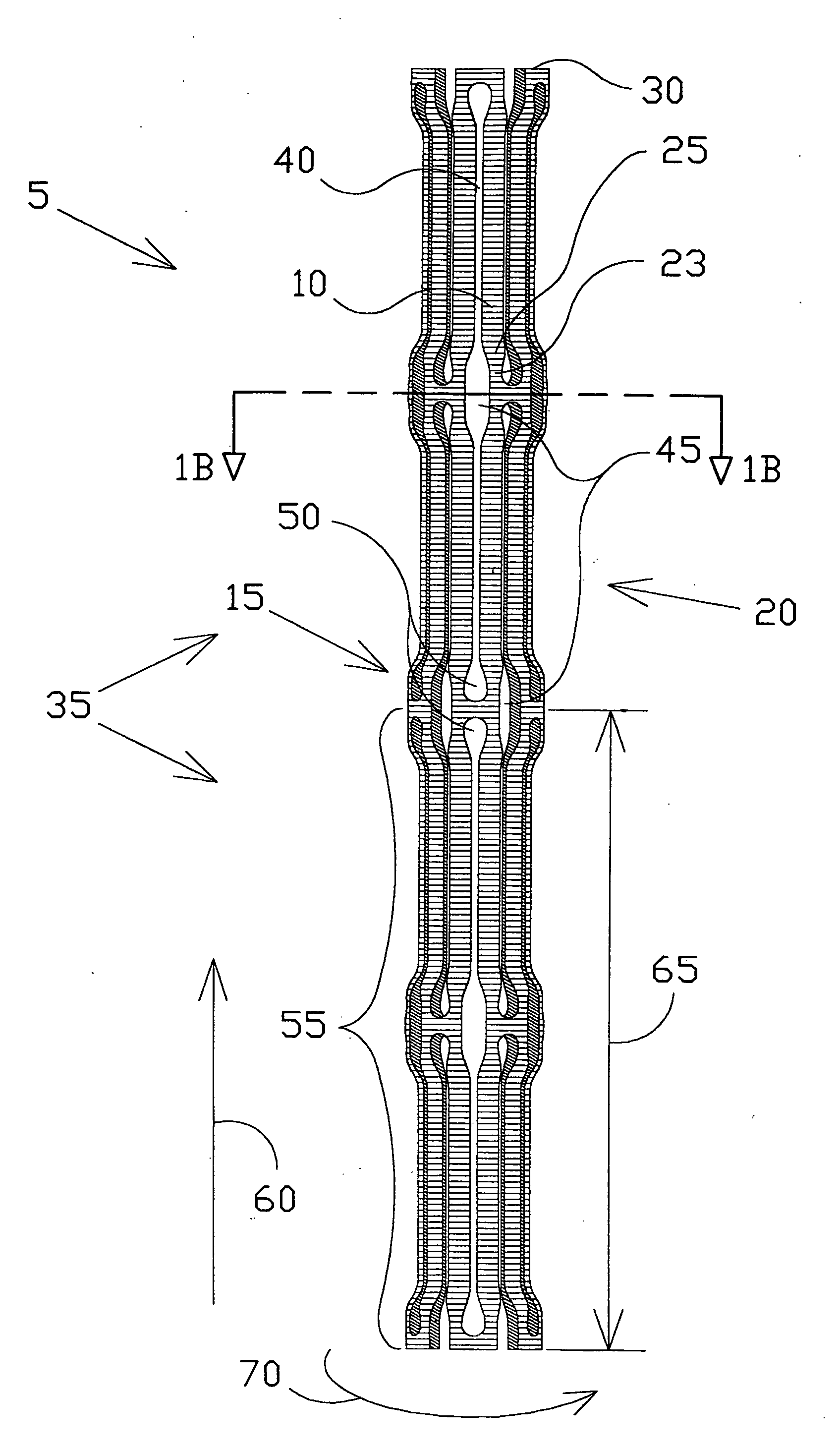
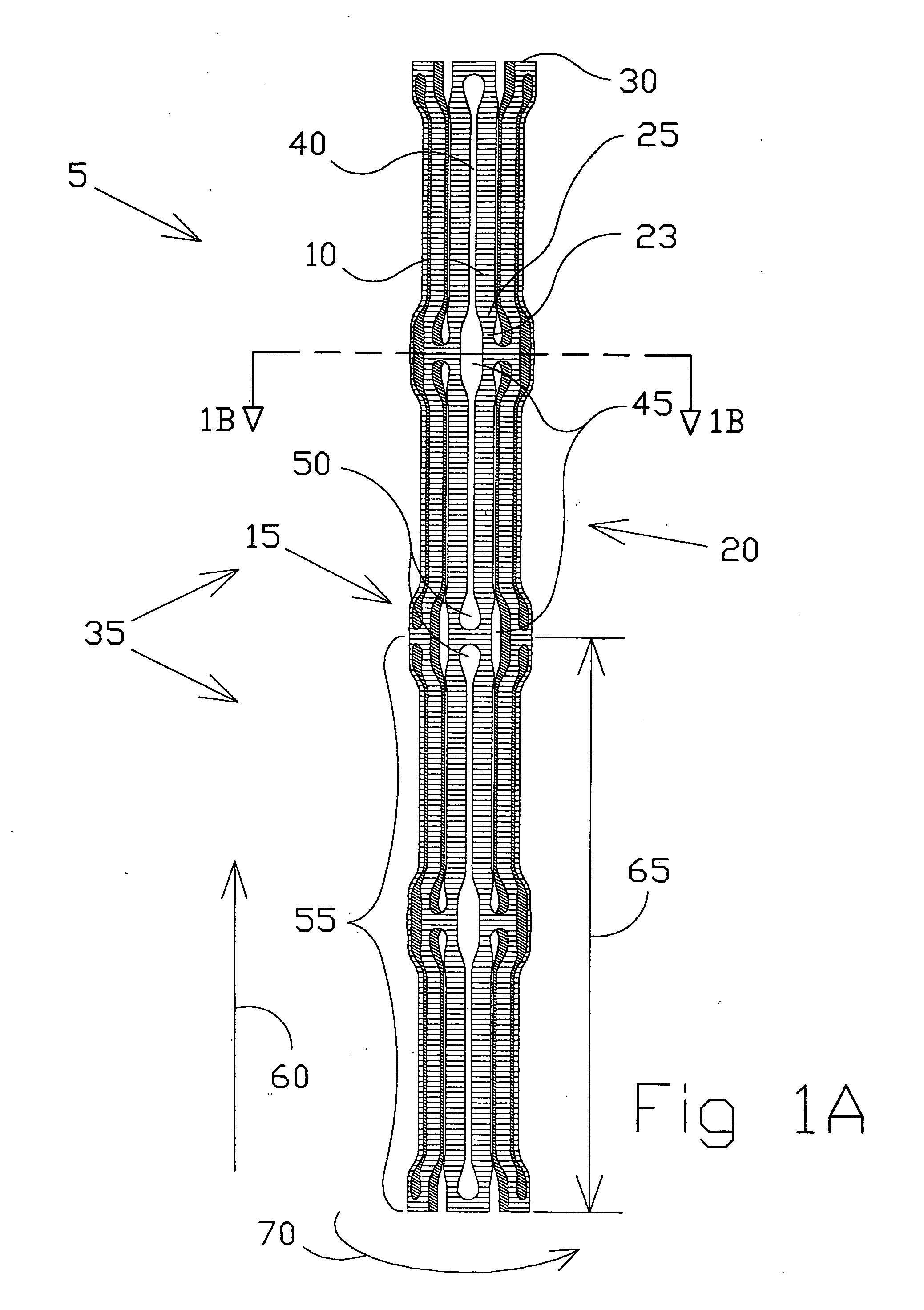
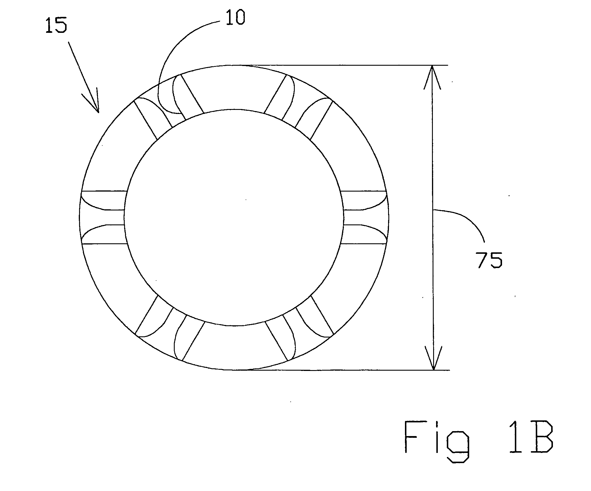
[0077]FIG. 1A shows one embodiment of a hinge stent 5 of the present invention in a nondeployed state or inserted state with struts 10 and nodes 15 joined together to form a stent section 20. A stent section 20 is made up entirely of nodes 15 and struts 10 extending throughout the stent section. Each node 15 of the hinge stent 5 includes at least one hinge 23 and at least two transition regions 25; ea...


PUM


Abstract

A balloon or self expandable endoprosthesis formed of a single or multiple joined stent sections. Each section has a node and strut structure extending throughout in order to uncouple expansion forces of the stent to hold a blood vessel outward from crush forces that resist the formation of an oval shape during crush deformation. The hinge can bend in the direction of a uniformly curved surface of the stent but not in the radial direction. The strut can bend in the radial direction but not in the uniformly curved surface of the stent. The widths, lengths, and radial dimensions of the hinges and struts provide a balloon-expandable hinge stent that is non-crushable. For a self-expanding stent the hinge and strut dimensions provide expansion forces that are controlled independently from crush forces. Expansion properties are determined by the hinge dimensions and crush properties are determined independently by strut dimensions.

Description

BACKGROUND OF THE INVENTION[0001]1. Field of Invention[0002]The present invention relates to an expandable endoprosthesis that is placed within a tubular member of the human body to treat a region that is pathologically affected by supporting it or holding the tubular member outwards. More specifically the invention relates to an intravascular endoprosthesis placed within a blood vessel of the body generally at the site of a vessel lesion in order to provide a more widely open lumen and enhance patency of the vessel. The present invention further relates to a stent that can be used in blood vessels and tubular vessels of the body that have become stenotic or blocked by tissue or other material and require reestablishment of a lumen and maintenance of the lumen.[0003]2. Description of Prior Art[0004]Stents used to internally support tubular vessels of the body can generally be categorized into two groups, those that are mechanically expanded by an external device such as a balloon di...

Claims


Application Information

Patent Timeline
Patent Type & Authority Applications(United States)
IPC IPC(8): A61F2/82A61F2/00A61F2/90
CPCA61F2/88A61F2/91A61F2/915A61F2002/91541A61F2230/0054A61F2002/91558A61F2250/0036A61F2220/0016A61F2002/9155
Inventor DRASLER, WILLIAM JOSEPHTHIELEN, JOSEPH MICHAEL
Owner DRASLER WILLIAM JOSEPH
Why Eureka
Try Eureka