
Road paving machine

A paving machine and road technology, applied in the direction of roads, roads, road repairs, etc., can solve the problems of inability to use support devices, insufficient functions, etc.

Inactive Publication Date: 2003-05-21
ABG ALLG BAUMASCHINEN GMBH
View PDF0 Cites 12 Cited by
  • Summary
  • Abstract
  • Description
  • Claims
  • Application Information

AI Technical Summary

Problems solved by technology

However, due to the play and elasticity in the guide mechanism of the extendable screed, this effect has been significantly reduced, especially, in this area, it is not possible to use the supporting means as in the case of the screed which can be installed manually
Even if this is done, as described in the case of screeds that can be installed by hand, it is not sufficient

Method used


Image

  • Road paving machine
  • Road paving machine
  • Road paving machine

Examples


Embodiment Construction

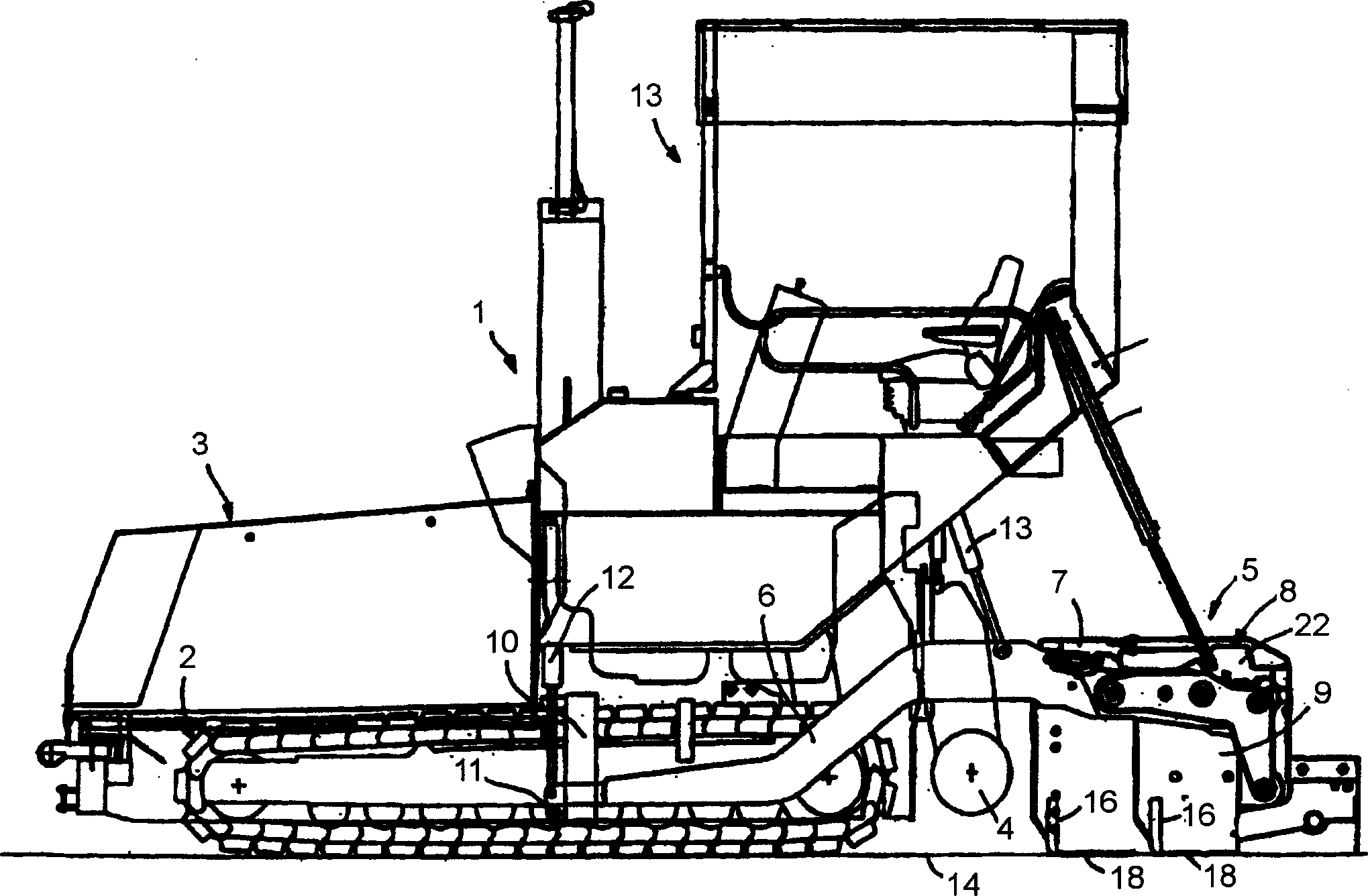
[0027] The paving machine shown in the non-working state for paving roads etc. comprises a chassis 1 with a crawler-type traveling mechanism 2 (which can be replaced by a wheel-type traveling mechanism), the chassis 1 has a hopper 3 at the front and At the rear there is a distributor screw 4, between which a conveyor (not visible) is arranged for transferring the mixture to be laid out from the hopper 3 via a delivery chute into the area of ​​the distributor screw 4 , the superstructure is located above the chute.

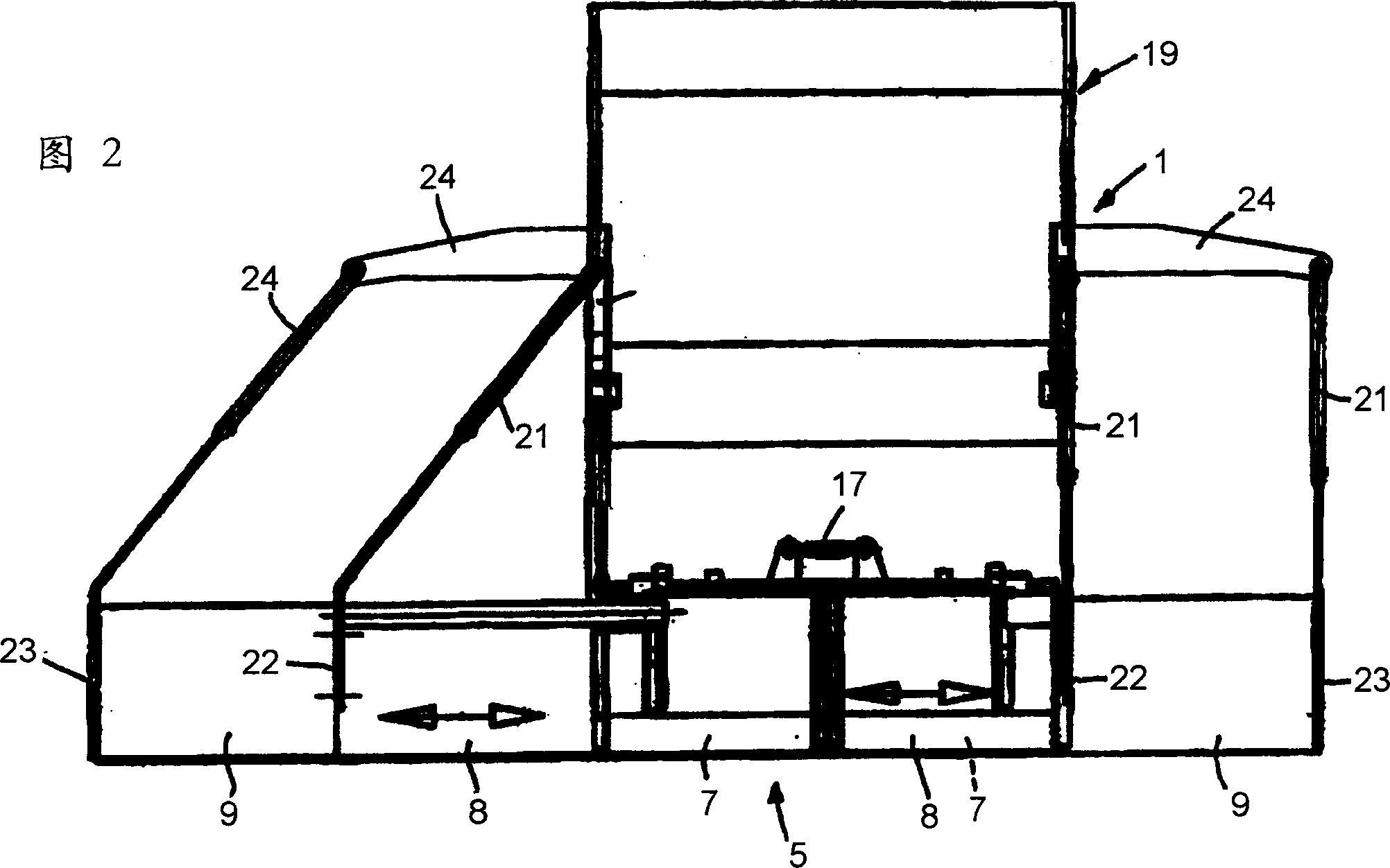
[0028] A floating screed 5 for floating laying of the mixture to be laid is articulated to the chassis 1 via trailing arms 6 . In laying direction, the screed 5 is located after the area of ​​the distributor screw conveyor 4 and may comprise a basic screed 7 and may also comprise extendable screeds which are transversely extendable with respect to said basic screed 7 and which are independent of each other 8. The basic screed 7 is divided centrally in a conventio...


PUM


Abstract

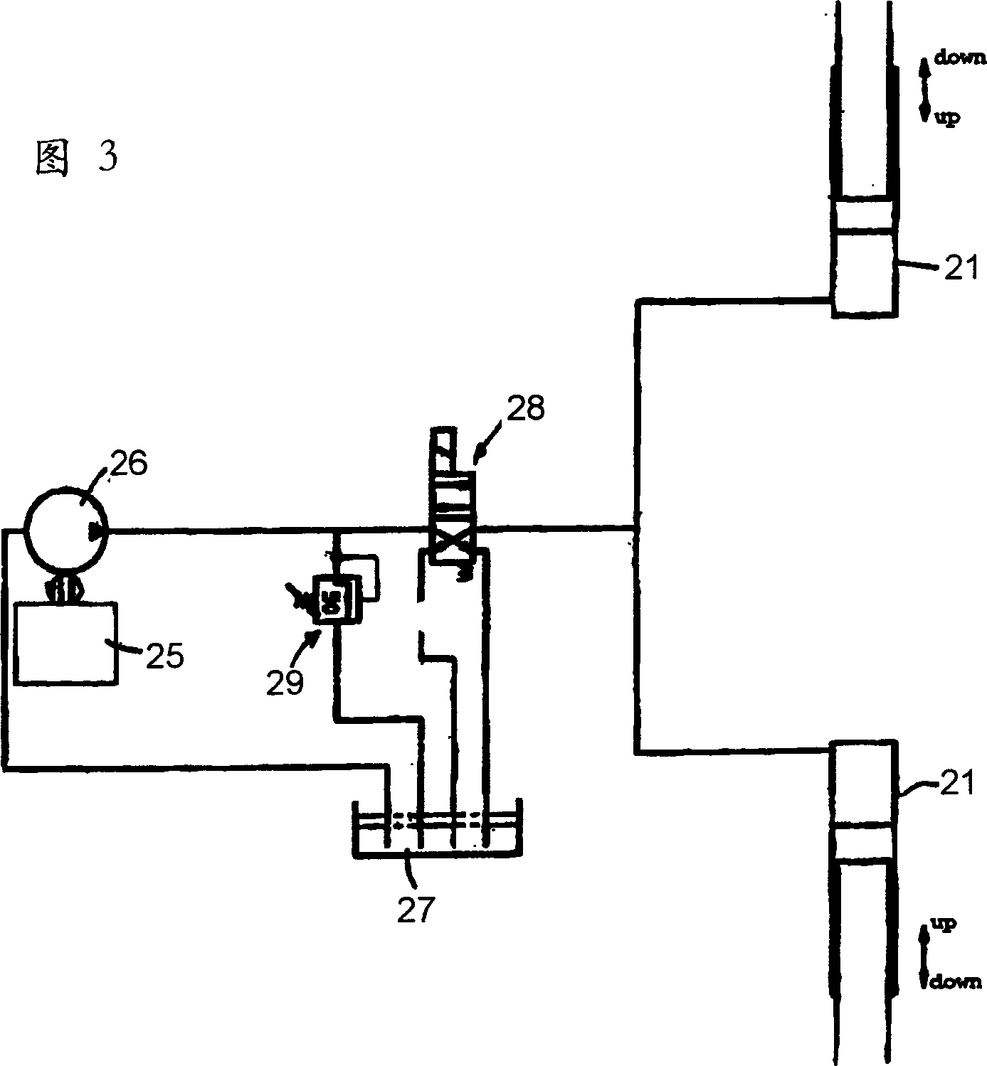
The invention relates to a paver for the paving of ground courses for roads or the like, having a chassis and a trailed floating screed which is articulated on the latter via tow arms and of which the angle of attack relative to the ground is capable of being adjusted via actuating cylinders and which comprises a basic screed and extendable screeds and / or attached screed parts, there being arranged between the rear region, as seen in the paving direction, of the chassis and the extendable screeds and / or the attached screed parts of each side at least one hydraulic supporting cylinder which, at the moment of start-up of the paver, is subjected to an adjustable hydraulic pressure.

Description

technical field [0001] The present invention relates to a paving machine for paving road surfaces such as roads. Background technique [0002] It is known that paving machines can pave roads with floating screeds, for example in road construction. Here, the screed is mounted centrally to the paver by means of two trailing arms located outside the paver frame or undercarriage, ie the screed is towed and adjustable in height. The screed itself floats at a positive angle of attack on the road surface to be paved, ie the front edge of the screed in the direction of travel is positioned higher than the rear edge. Positive angle of attack is generated by parameters such as mixing, tamping and vibratory compacting of the road carrying capacity, weight of the screed, speed of laying, etc. [0003] This positive angle of attack, and especially the metered inclination of the tamper, which is located in the front region of the screed, forms a "ramp" when viewed from the direction of ...

Claims


Application Information

Patent Timeline
Patent Type & Authority Applications(China)
IPC IPC(8): E01C19/48E01C19/40
CPCE01C19/40E01C2301/16E01C2301/14
Inventor 德克·海姆斯
Owner ABG ALLG BAUMASCHINEN GMBH
Learn More