
Short-focus lens and short-focus optical system

A lens and short-focus technology, which is applied in the field of short-focus lenses and short-focus optical systems, can solve the problems of difficult processing of aspheric mirrors, high error installation accuracy requirements, and low product manufacturing yields, and achieve good image projection effects. Effect

Pending Publication Date: 2021-06-01
沂普光电(天津)有限公司
View PDF0 Cites 8 Cited by
  • Summary
  • Abstract
  • Description
  • Claims
  • Application Information

AI Technical Summary

Problems solved by technology

[0003] In order to achieve a smaller equipment volume in the existing short-focus lens optical system, more aspheric mirrors are usually added to the optical lens group to process the optical path, but the manufacturing cost of the equipment is high due to the difficulty of processing aspheric mirrors. In addition, because the aspheric mirror is more sensitive to errors, the aspheric mirror has higher requirements for installation accuracy during installation, which is more likely to lead to the problem of low manufacturing yield of the final product and the inability to carry out mass production
There are also a small number of lenses that directly use a large number of plastic aspheric mirrors in order to reduce costs. However, plastic aspherical mirrors will be deformed due to high temperature and heat during product use, which will affect the final presentation of the picture.
At present, there is no ultra-short-focus lens on the market that can overcome the above shortcomings at the same time.

Method used


Image

  • Short-focus lens and short-focus optical system
  • Short-focus lens and short-focus optical system
  • Short-focus lens and short-focus optical system

Examples


Embodiment Construction

[0031] The following will clearly and completely describe the technical solutions in the embodiments of the present invention with reference to the accompanying drawings in the embodiments of the present invention. Obviously, the described embodiments are only some, not all, embodiments of the present invention. Based on the embodiments of the present invention, all other embodiments obtained by persons of ordinary skill in the art without making creative efforts belong to the protection scope of the present invention.

[0032] It should be noted that when a component is said to be "fixed" to another component, it can be directly on the other component or there can also be an intervening component. When a component is said to be "connected" to another component, it may be directly connected to the other component or there may be intervening components at the same time. When a component is said to be "set on" another component, it may be set directly on the other component or t...


PUM


Abstract

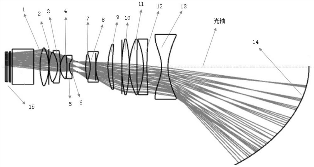
The invention relates to the technical field of short-focus lenses, and discloses a short-focus lens, which comprises a shell, and a refraction lens group and an aspheric reflector which are arranged in an inner cavity of the shell and are sequentially arranged in the refraction projection direction of a light path, the refraction lens group comprises a rear lens group, a middle lens group and a front lens group, wherein the rear lens group, the middle lens group and the front lens group are arranged along the optical axis in the direction from the image incident side to the image emergent side and can move back and forth in the optical axis direction, the focal power of the rear lens group is positive, the focal power of the middle lens group is negative, and the focal power of the front lens group is negative. According to the optical lens provided by the invention, the rear group and the middle group of lens groups close to one side of the image source emitter are spherical mirrors made of glass, and one lens and the reflector in the front group of lens groups far away from one side of the image source emitter are aspheric lenses made of plastic. The processing cost can be reduced by reducing the number of the aspherical lenses, and meanwhile, the distortion degree of a picture under a high-temperature condition can be reduced by controlling the material, the surface type and the placement position of each lens.

Description

technical field [0001] The invention relates to the technical field of short-focus lenses, in particular to a short-focus lens and a short-focus optical system. Background technique [0002] In recent years, with the development of projection technology, projectors have been widely used in various scenarios. Among them, ultra-short-focus projection equipment is widely used in home and office fields due to its short distance projection and large screen characteristics. [0003] In order to achieve a smaller equipment volume in the existing short-focus lens optical system, more aspheric mirrors are usually added to the optical lens group to process the optical path, but the manufacturing cost of the equipment is high due to the difficulty of processing aspheric mirrors. In addition, since the aspheric mirror is more sensitive to errors, the installation accuracy of the aspheric mirror is relatively high, which is also more likely to lead to the problem that the final product h...

Claims


Application Information

Patent Timeline
Patent Type & Authority Applications(China)
IPC IPC(8): G02B13/00G02B13/18G02B13/16G02B13/24G03B21/14G03B21/28
CPCG02B13/0015G02B13/0045G02B13/006G02B13/0065G02B13/16G02B13/24G03B21/14G03B21/142G03B21/28
Inventor 郭跃武徐航宇侯健
Owner 沂普光电(天津)有限公司
Learn More