Connector shelter plate

A technology of connectors and shielding plates, applied in the direction of connections, parts of connecting devices, fixed/insulated contact members, etc.

Inactive Publication Date: 2003-08-20
TE CONNECTIVITY GERMANY GMBH
View PDF0 Cites 5 Cited by
  • Summary
  • Abstract
  • Description
  • Claims
  • Application Information

AI Technical Summary

Problems solved by technology

Therefore, a large space is required between the internal connector 100 and the dust-proof shielding plate 120

Method used


Image

  • Connector shelter plate
  • Connector shelter plate
  • Connector shelter plate

Examples


Embodiment Construction

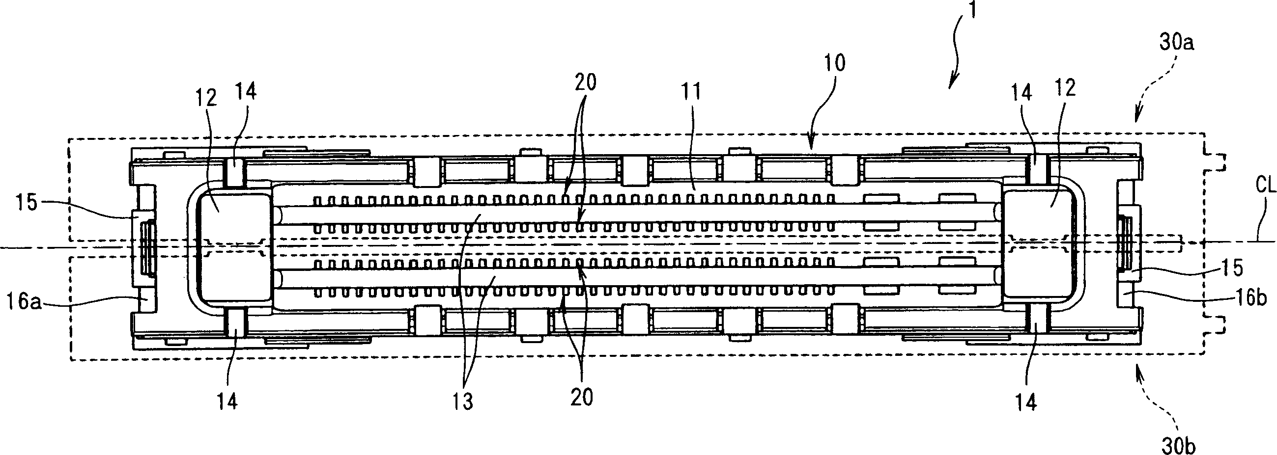
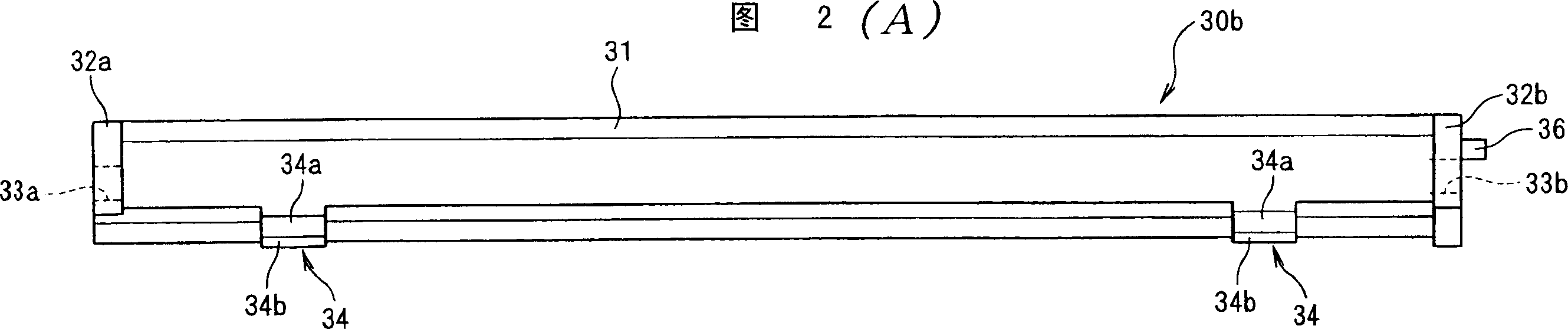
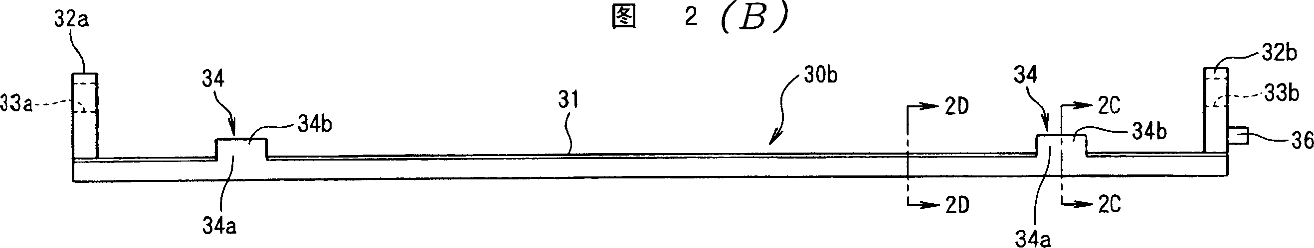
[0027] Hereinafter, embodiments of the present invention will be described with reference to the drawings. figure 1 It is a plan view of a connector, the shutter of the present invention opens and closes the connector. exist figure 1 In , the pair of dust-proof baffles are indicated by dotted lines. Figure 2 shows that when the figure 1 Figure 2(A) shows the bottom view, Figure 2(B) shows the rear view, and Figure 2(C) shows the dust shield on one side when used in the connector shown in 2(B) is a sectional view taken along line 2C-2C, and FIG. 2(D) shows a sectional view taken along line 2D-2D in FIG. 2(B). Fig. 3 shows the state that this pair of dust-proof baffles are installed on the shell, Fig. 3(A) shows the bottom view, Fig. 3(B) shows the rear view, Fig. 3(C) shows side view. Figure 4 shows the figure 1Figure 4(A) shows a front view and Figure 4(B) shows a right side view. Figure 5 to Figure 10 are cross-sectional views showing the mating action of the mating c...


PUM


Abstract

The present invention provides a connector shutter which makes it possible to reduce the space between the connector and the shutters. The connector shutters 30a and 30b are installed in the housing 38 of an electronic device so that the mating recesses 11 and 12 of the connector 1 are opened and closed by these connector shutters 30a and 30b. These connector shutters 30a and 30b are caused to pivot as a result of the tip ends of the connector shutters being contacted by the guide parts 53 of the mating connector 40, so that the mating recesses 11 and 12 of the connector 1 are opened. The pivoting shafts (shaft holes 33a and 33b) of the connector shutters 30a and 30b are disposed facing the end surfaces 16a and 16b of the connector 1 at both ends of the connector 1 with respect to the lengthwise direction, and the contact parts 34 of the tip ends of the shutters 30a and 30b that are contacted by the guide parts 53 include protruding parts 34b that protrude further than the other portions of these tip ends.

Description

technical field [0001] The present invention relates to a connector shield that opens and closes a mating recess of a connector. Background technique [0002] Generally, in order to connect external devices to electronic devices such as notebook personal computers, connectors are provided on these electronic devices and external devices to mate with each other. Furthermore, in the case of an electronic device such as a notebook computer, there is a danger that, in a state where no external device is connected, foreign objects will enter the mating area of ​​the connector (the connector is used to mate with the mating connector). In the mating recess, and bonded to the contact of the connector; therefore, a dust-proof shield is provided to prevent such external foreign matter from entering the mating recess. [0003] FIG. 11 shows a conventional example in which a dust-proof shutter is mounted on an open portion of a case of an electronic device (see Japanese Patent Applicat...

Claims


Application Information

Patent Timeline
Patent Type & Authority Applications(China)
IPC IPC(8): H01R13/52H01R13/453
CPCH01R13/4532H01R13/42
Inventor 桥本信一
Owner TE CONNECTIVITY GERMANY GMBH
Why Eureka
Try Eureka