A piezoelectric micropump

A micro-pump, piezoelectric technology, applied in variable capacity pump parts, pumps, pump components, etc., can solve the problems of small valve opening, large flow resistance, complicated valve bonding process, etc., to achieve enlarged opening degree, simplification of the assembly process, and the effect of facilitating industrialized mass production

Active Publication Date: 2022-08-02
HUAZHONG UNIV OF SCI & TECH
View PDF5 Cites 0 Cited by
  • Summary
  • Abstract
  • Description
  • Claims
  • Application Information

AI Technical Summary

Problems solved by technology

[0005] In view of the above defects or improvement needs of the prior art, the present invention provides a piezoelectric micropump, which solves the problems in the prior art that the valve plate opening of the piezoelectric pump is small, the flow resistance is large, and the valve plate bonding process is complicated.

Method used


Image

  • A piezoelectric micropump
  • A piezoelectric micropump
  • A piezoelectric micropump

Examples


Embodiment Construction

[0030] In order to make the objectives, technical solutions and advantages of the present invention clearer, the present invention will be further described in detail below with reference to the accompanying drawings and embodiments. It should be understood that the specific embodiments described herein are only used to explain the present invention, but not to limit the present invention. In addition, the technical features involved in the various embodiments of the present invention described below can be combined with each other as long as there is no conflict with each other.

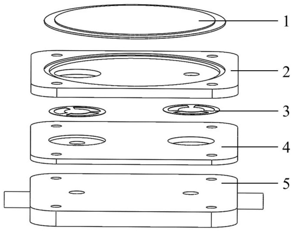
[0031] figure 1 It is an anatomical diagram of a preferred embodiment of the piezoelectric micropump of the present invention, including a piezoelectric vibrator 1 , an upper pump body 2 , a valve plate 3 , a lower pump body 4 and a base 5 .

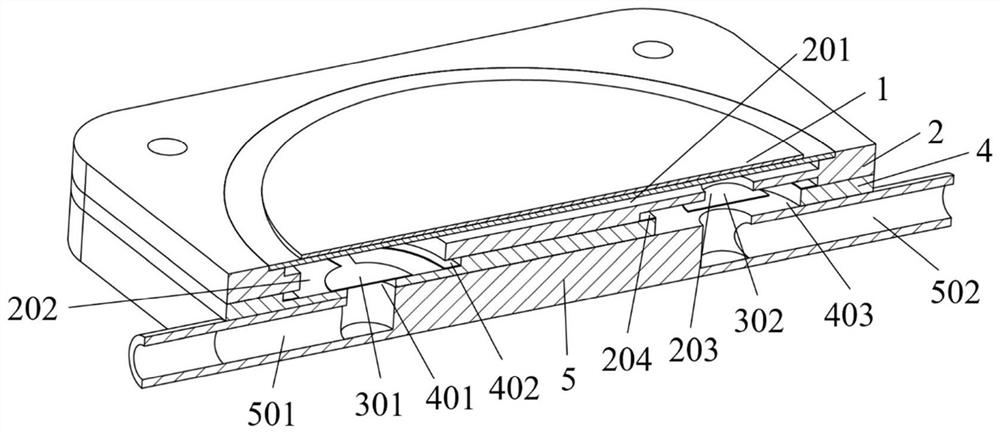
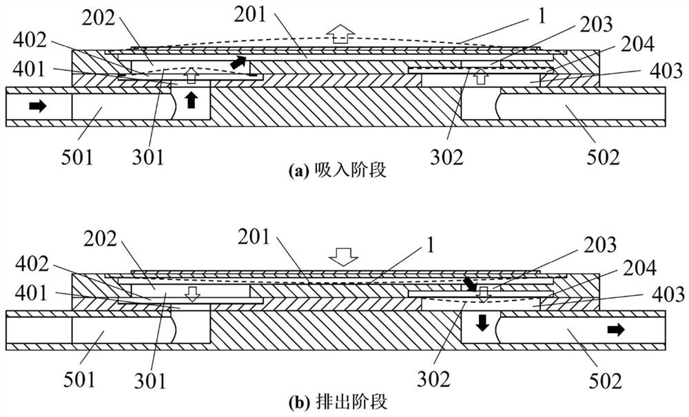
[0032] see figure 2 , the valve plate 3 includes an inlet valve 301 and an outlet valve 302; the piezoelectric vibrator 1 cooperates with the upper pump bo...


PUM


Abstract

The invention discloses a piezoelectric micro-pump, comprising a piezoelectric vibrator, an upper pump body, a lower pump body and a valve plate. The piezoelectric vibrator and the upper pump body form a pump cavity; The valve cavity is formed with an inlet and outlet, and the valve plate is arranged in the valve cavity with a certain gap for free movement up and down. During the opening process of the valve plate, the first stage is the overall translation, and the second stage is the valve plate deformation. The invention not only expands the opening degree of the valve plate, but also enables the valve plate and the pump chamber pressure to have good followability, and solves the problem that the valve plate of the piezoelectric pump has a small opening degree, large flow resistance, and sticking of the valve plate in the prior art. The problem of complex process.

Description

technical field [0001] The invention belongs to the technical field of micro-pumps, and more particularly, relates to a piezoelectric micro-pump. Background technique [0002] Micropumps are widely used in biomedical, chemical analysis and electronic chip cooling as a kind of microfluidic driving device. Among many micro-pumps, piezoelectric micro-pumps are one of the most promising micro-pumps due to their remarkable advantages such as compact structure, low power consumption, high control precision and low noise. [0003] The working principle of the piezoelectric micropump is as follows: the piezoelectric vibrator is deformed under the action of the alternating voltage, which changes the volume of the pump cavity, and the change of the pressure in the pump cavity drives the movement of the valve plate, so that the inlet and outlet flow channels are opened or closed. Produces the effect of one-way circulation. In this reciprocation, the fluid is sucked into the pump cham...

Claims


Application Information

Patent Timeline
Patent Type & Authority Patents(China)
IPC IPC(8): F04B43/04F04B53/10
CPCF04B43/046F04B53/102F04B53/108
Inventor 罗小兵范义文赵伟贤张信峰廖唯唯
Owner HUAZHONG UNIV OF SCI & TECH
Why Eureka
Try Eureka