Single-cavity axial-flow piezoelectric pump with valve and driving method

An axial flow, piezoelectric pump technology, applied in the direction of variable displacement pump parts, pumps with flexible working elements, parts of pumping devices for elastic fluids, etc. Limiting the maximum opening degree of the valve, affecting the stable output of the pump, etc., to achieve the effect of increasing the opening degree, increasing the output flow, and improving the flow output

Active Publication Date: 2021-03-23
CHANGZHOU INST OF TECH
View PDF7 Cites 0 Cited by
  • Summary
  • Abstract
  • Description
  • Claims
  • Application Information

AI Technical Summary

Problems solved by technology

[0003] The existing single-cavity piezoelectric pump is limited by the driving ability of the piezoelectric vibrator, the self-priming performance is poor when transporting liquid, and the ability to discharge air bubbles in the cavity is not strong, and the residual air bubbles affect the stable output of the pump
In terms of structural design, the inlet and outlet valves of current single-chamber piezoelectric pumps are generally located in the cylindrical pump chamber, and the position is symmetrically distributed with the axis of the cylindrical pump chamber as the axis of symmetry, which makes the position of the valve not in the pump chamber The maximum pressure difference limits the maximum opening of the valve and affects the output capacity of the pump

Method used


Image

  • Single-cavity axial-flow piezoelectric pump with valve and driving method
  • Single-cavity axial-flow piezoelectric pump with valve and driving method
  • Single-cavity axial-flow piezoelectric pump with valve and driving method

Examples


Embodiment

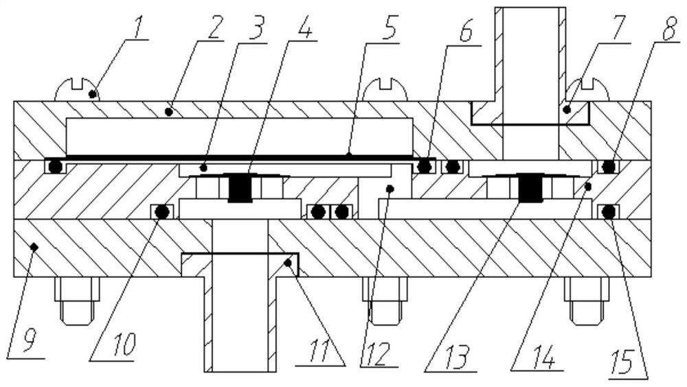
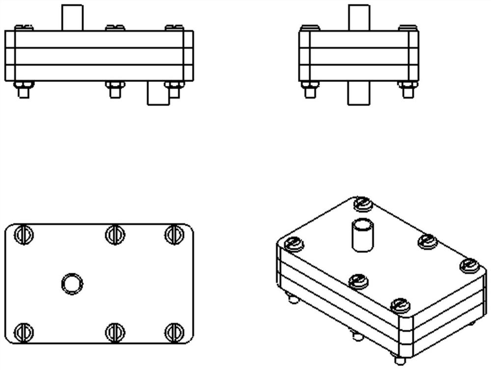
[0027] The invention discloses a single-cavity axial-flow piezoelectric pump with a valve. The pump body structure is mainly composed of three parts, namely the upper cover for fixing the piezoelectric vibrator, the intermediate body with cavity structure and passive stop valve, and the lower cover for pressing and sealing.

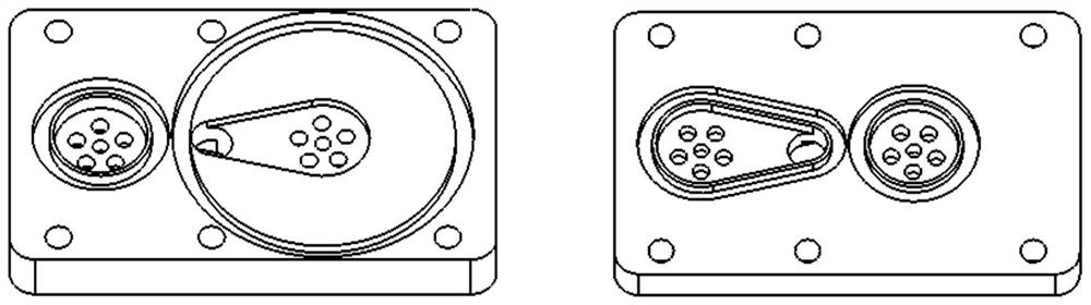
[0028] Such as Figure 1-4 As shown, the alternating voltage acts on the piezoelectric vibrator for one cycle. When the circular piezoelectric vibrator 5 vibrates upward, the volume of the pump chamber 3 becomes larger, and the external ambient pressure acting on the inlet valve 4 is greater than the internal pressure of the pump chamber. , the inlet valve is gradually opened, and the fluid enters the pump chamber through inlet 11. When the piezoelectric vibrator vibrates downward, the volume of the pump chamber becomes smaller, the external ambient pressure acting on the inlet valve is lower than the internal pressure of the pump chamber, the outlet val...


PUM


Abstract

The invention discloses a single-cavity axial flow type valve piezoelectric pump and a driving method. An upper cover, a middle body and a lower cover with a sealing function of a fixed piezoelectricvibrator are sequentially arranged from top to bottom; the middle body is provided with a cylindrical cavity structure and a passive stop valve; a pump cavity is positioned in the middle body, a circular piezoelectric vibrator is positioned in the cylindrical cavity, an inlet valve, connected to an inlet joint, at the lower part of the circular piezoelectric vibrator is positioned on the central axis of the cylindrical cavity, so that the axis of the inlet pipe is perpendicular to the piezoelectric vibrator to form an axial flow inlet mode; and an outlet joint is arranged on the upper cover and is connected to the pump cavity through an outlet connecting channel, and the direction of an outlet pipe is consistent with the valve opening direction. According to the single-cavity axial flow type valve piezoelectric pump, the inlet valve is arranged at the central position of the cylinder pump cavity, that is, the pressure difference change in the cavity is largest, the opening degree of the valve is increased, and the outflow capability is increased; and the outlet valve is arranged outside the cylinder pump cavity, so that the discharge of the bubbles during liquid delivery is facilitated, the axis of the inlet pipe and the axis of the outlet pipe are perpendicular to the surface of the piezoelectric vibrator, so that the energy loss in the flowing process is reduced.

Description

technical field [0001] The invention relates to the field of fluid machinery, in particular to a single-cavity axial-flow piezoelectric pump with a valve and a driving method. Background technique [0002] The valved piezoelectric pump uses the piezoelectric vibrator to generate reciprocating vibration under the action of alternating voltage. The change in the volume of the pump chamber forms a constantly changing pressure difference on both sides of the passive stop valve, driving the fluid to flow in from the inlet valve of the pump, and the outlet valve outflow. Under the same conditions, increasing the opening degree of the valve and reducing the energy loss of the fluid flowing in the cavity will increase the net output flow of the piezoelectric pump. [0003] The existing single-cavity piezoelectric pump is limited by the driving ability of the piezoelectric vibrator, and its self-priming performance is poor when transporting liquid, and its ability to discharge air b...

Claims


Application Information

Patent Timeline
Patent Type & Authority Patents(China)
IPC IPC(8): F04B43/04F04B53/10F04B53/16
CPCF04B43/046F04B53/10F04B53/16
Inventor 孙晓锋武之炜黄成陈永将
Owner CHANGZHOU INST OF TECH
Why Eureka
Try Eureka