Control method, control device and cooking appliance

A technology of cooking utensils and control methods, applied in the fields of control devices, cooking utensils, and control methods, can solve the problems of uncontrollable steam exhaust speed, inability to close steam exhaust valves, and inability to guarantee

Active Publication Date: 2019-03-08
FOSHAN SHUNDE MIDEA ELECTRICAL HEATING APPLIANCES MFG CO LTD +1
View PDF12 Cites 0 Cited by
  • Summary
  • Abstract
  • Description
  • Claims
  • Application Information

AI Technical Summary

Problems solved by technology

[0002] Existing cooking appliances, such as electric pressure cookers, usually realize the steam exhaust function of the electric pressure cooker by manually opening the steam exhaust valve on the electric pressure cooker after the cooking is completed, so as to discharge the water vapor in the pot. The medium pot maintains a certain preset pressure, which causes the pressure in the pot to decrease instantly when the user opens the exhaust valve, which easily causes the food in the pot to overflow along the steam channel on the exhaust valve, and at the same time makes it impossible for the user to close the exhaust valve. The steam valve affects the user's experience; some existing electric pressure cookers slow down the overflow of food in the pot when the exhaust valve is opened to a certain extent by controlling the opening and closing of the exhaust valve. However, the above method will also cause The exhaust time is too long, the exhaust speed is uncontrollable, etc., and there is no guarantee that there will be no food spillage when the exhaust valve is opened when cooking a large amount of porridge

Method used


Image

  • Control method, control device and cooking appliance
  • Control method, control device and cooking appliance
  • Control method, control device and cooking appliance

Examples


Embodiment Construction

[0029] In order to understand the above-mentioned purpose, features and advantages of the present invention more clearly, the present invention will be further described in detail below in conjunction with the accompanying drawings and specific embodiments. It should be noted that, in the case of no conflict, the embodiments of the present application and the features in the embodiments can be combined with each other.

[0030] In the following description, many specific details are set forth in order to fully understand the present invention. However, the present invention can also be implemented in other ways than described here. Therefore, the protection scope of the present invention is not limited by the specific implementation disclosed below. Example limitations.

[0031] Refer to the attached Figures 1 to 4 The control method, control device and cooking appliance provided according to some embodiments of the present invention are described.

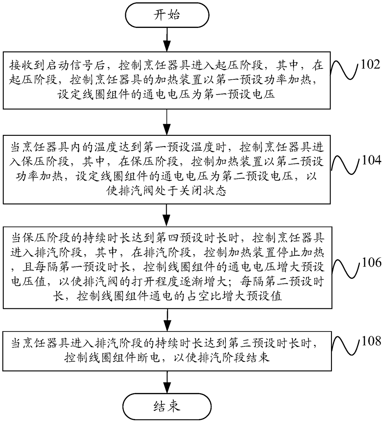
[0032] Such as figure 1 ...


PUM


Abstract

The invention provides a control method, a control device and a cooking utensil. The control method is used for controlling the cooking utensil; a steam exhaust valve and a coil assembly are arranged on an upper cover of the cooking utensil, and a permanent magnet is arranged on the steam exhaust valve and can be subjected to acting force of a magnetic field generated when the coil assembly is electrified. The control method includes the steps that after the cooking utensil enters a steam exhaust stage, the electrification voltage of the coil assembly is controlled to be increased or decreased by a preset voltage value every first preset duration to change the acting force, which the permanent magnet is subjected to, of the magnetic field generated when the coil assembly is electrified so that the switching-on degree of the steam exhaust valve can be increased gradually. According to the control method, the switching-on degree of the steam exhaust valve is controlled by dynamically adjusting the electrification voltage, generated after the cooking utensil enters the steam exhaust stage, of the coil assembly; besides, the pressure in the cooking utensil is gradually decreased along with the increase of the steam exhaust duration, the switching-on degree of the steam exhaust valve is controlled to be increased, and thus the effect of rapid and stable steam exhaust and pressure decrease in the cooking utensil is achieved.

Description

technical field [0001] The invention relates to the field of kitchen utensils, and more specifically, to a control method, a control device and a cooking utensil. Background technique [0002] Existing cooking appliances, such as electric pressure cookers, usually realize the steam exhaust function of the electric pressure cooker by manually opening the steam exhaust valve on the electric pressure cooker after the cooking is completed, so as to discharge the water vapor in the pot. The medium pot maintains a certain preset pressure, which causes the pressure in the pot to decrease instantly when the user opens the exhaust valve, which easily causes the food in the pot to overflow along the steam channel on the exhaust valve, and at the same time makes it impossible for the user to close the exhaust valve. The steam valve affects the user's experience; some existing electric pressure cookers slow down the overflow of food in the pot when the exhaust valve is opened to a certa...

Claims


Application Information

Patent Timeline
Patent Type & Authority Patents(China)
IPC IPC(8): A47J36/38A47J36/24A47J27/09A47J27/08
Inventor 王博达任蓬勃李新峰
Owner FOSHAN SHUNDE MIDEA ELECTRICAL HEATING APPLIANCES MFG CO LTD
Why Eureka
Try Eureka