Fire-fighting smoke exhaust fan capable of achieving multi-angle adjustment and independent control

A technology of independent control and smoke exhaust fan, which is applied in the direction of pump control, mechanical equipment, machine/engine, etc. It can solve the problems of simultaneous air exhaust and smoke exhaust from multiple angles and directions, the inability to realize multiple angles, and single design, etc., to achieve Strong practicality and creativity, improve work efficiency, reduce the effect of intensity

Inactive Publication Date: 2021-01-08
杭州艾洋洋信息科技有限公司
View PDF0 Cites 2 Cited by
  • Summary
  • Abstract
  • Description
  • Claims
  • Application Information

AI Technical Summary

Problems solved by technology

However, the wind power output end of the existing fire-fighting smoke exhaust machine is generally designed in a single way, which can only discharge air from a single outlet, and cannot achieve multi-angle, multi-direction and independent control of the effect of the size of the wind. When it comes to the smoke exhaust machine, the defects of the existing technology are fully exposed, and it is impossible to realize simultaneous air and smoke exhaust from multiple angles and directions. Therefore, the existing technology has certain defects and disadvantages in the actual use process.

Method used


Image

  • Fire-fighting smoke exhaust fan capable of achieving multi-angle adjustment and independent control
  • Fire-fighting smoke exhaust fan capable of achieving multi-angle adjustment and independent control
  • Fire-fighting smoke exhaust fan capable of achieving multi-angle adjustment and independent control

Examples


Embodiment Construction

[0036] The following will clearly and completely describe the technical solutions in the embodiments of the present invention with reference to the accompanying drawings in the embodiments of the present invention. Obviously, the described embodiments are only some, not all, embodiments of the present invention. Based on the embodiments of the present invention, all other embodiments obtained by persons of ordinary skill in the art without making creative efforts belong to the protection scope of the present invention.

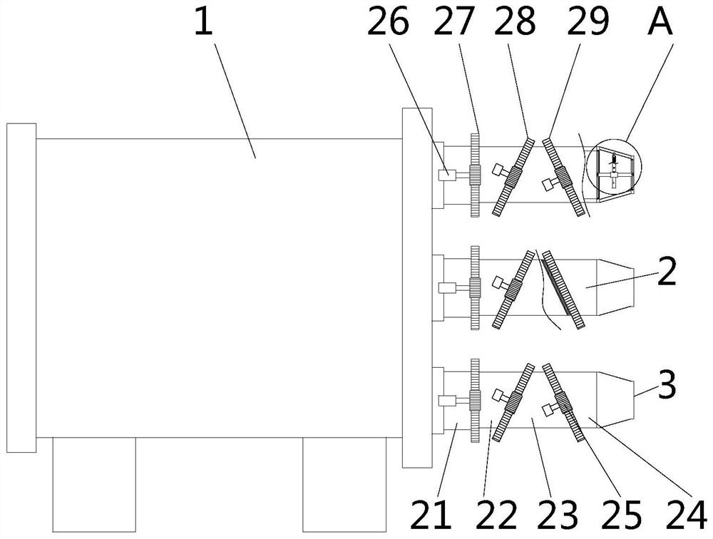
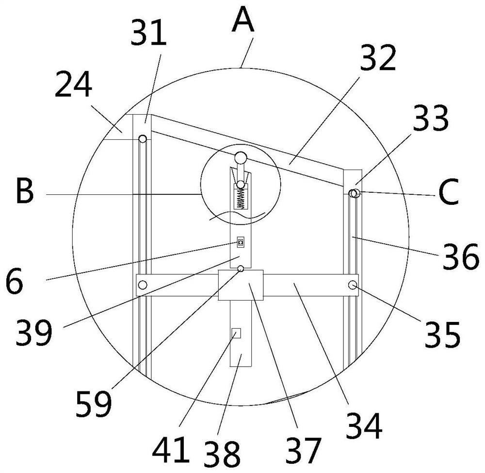
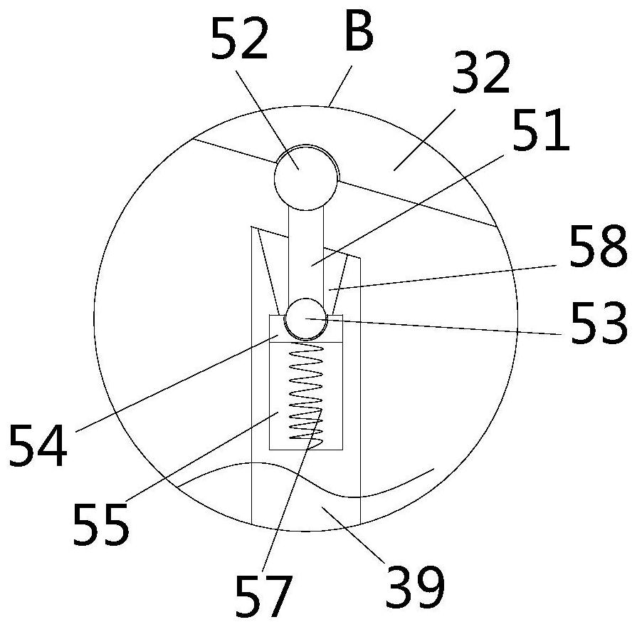
[0037] see Figure 1-11, the present invention provides a technical solution: a multi-angle adjustable and individually controlled fire smoke exhaust fan, including a body 1, the body 1 is the body of the fire smoke exhaust machine, and the body 1 is a prior art, so it will not be repeated here. On the output end surface on the right side of the machine body 1, there are six groups of air outlet devices 2 arranged in a circular array. The air outlet device 2 i...


PUM


Abstract

The invention relates to the technical field of smoke exhaust fans, and discloses a fire-fighting smoke exhaust fan capable of achieving multi-angle adjustment and independent control. The fire-fighting smoke exhaust fan capable of achieving multi-angle adjustment and independent control comprises a machine body, six sets of air outlet devices distributed in an annular array are arranged on the output end face of the right side of the machine body, the air outlet devices comprise first air ducts, second air ducts, third air ducts and fourth air ducts, the six sets of first air ducts are fixedly installed on the output end face of the right side of the first air ducts in an annular array mode. According to the fire-fighting smoke exhaust fan capable of achieving multi-angle adjustment and independent control, the air outlet devices are arranged, and the effect that the second air ducts, the third air ducts and the fourth air ducts are driven by output of respective servo motors is achieved, so that the second air ducts, the third air ducts and the fourth air ducts are matched with one another for use, and all the six sets of air outlet devices can blow air at multiple angles and inmultiple directions independently; and compared with single air outlet of a machine body in the prior art, the working efficiency of the machine body is improved, meanwhile, the fire-fighting smoke exhaust efficiency is improved, the height adjustment or angle adjustment does not need to be carried out on the output end of the machine body, and the labor intensity of workers is reduced.

Description

technical field [0001] The invention relates to the technical field of smoke exhaust fans, in particular to a multi-angle adjustable and individually controlled fire smoke exhaust fan. Background technique [0002] As the name suggests, the fire smoke exhaust fan is used for fire smoke exhaust. It uses the fan to rotate and blow out the wind to exhaust the air, so as to achieve the effect of smoke exhaust. However, the wind power output end of the existing fire-fighting smoke exhaust machine is generally designed in a single way, which can only discharge air from a single outlet, and cannot achieve multi-angle, multi-direction and independent control of the effect of the size of the wind. When it comes to the smoke exhaust machine, the defects of the prior art are fully exposed, and it is impossible to simultaneously discharge air and smoke from multiple angles and directions. Therefore, the existing technology has certain defects and disadvantages in the actual use process....

Claims


Application Information

Patent Timeline
IPC IPC(8): F04D29/40F04D27/00F04D29/70
CPCF04D27/002F04D29/403F04D29/703
Inventor 刘俊
Owner 杭州艾洋洋信息科技有限公司
Why Eureka
Try Eureka