Control device and hydraulic pilot control

一种控制设备、先导控制阀的技术,应用在机械设备、流体压力致动装置、流体压力致动系统安全等方向,能够解决不能容易地传送、供应管线不能够减压、复杂等问题

Inactive Publication Date: 2012-11-14
ROBERT BOSCH GMBH +1
View PDF2 Cites 0 Cited by
  • Summary
  • Abstract
  • Description
  • Claims
  • Application Information

AI Technical Summary

Problems solved by technology

In such valves a complex and / or expensive construction is disadvantageous
Also said configuration cannot be easily transferred to a pilot control valve formed as a pressure reducing valve
Also, in case of continuous actuation due to failure of the control electronics of the 3 / 2 directional valve, the supply line will not be able to decompress

Method used


Image

  • Control device and hydraulic pilot control
  • Control device and hydraulic pilot control
  • Control device and hydraulic pilot control

Examples


Embodiment Construction

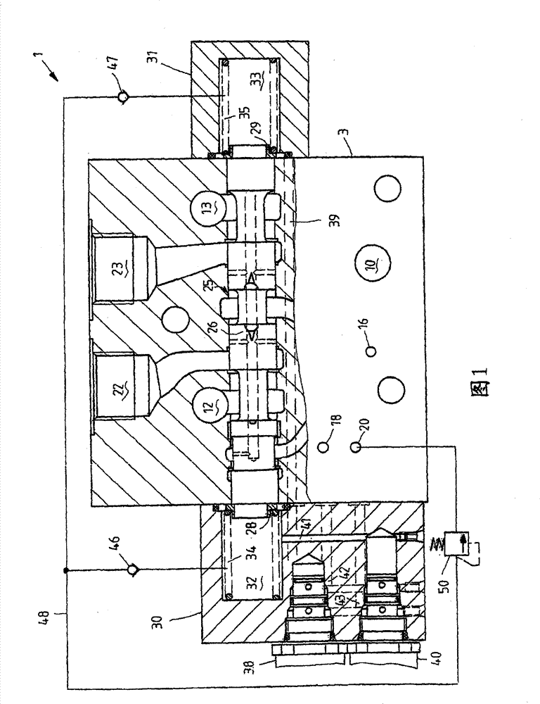
[0030] will now refer to figure 1 The invention is described in terms of a directional valve disc as used, for example, in a hydraulic control block. However, the invention is not limited to this particular configuration of the hydraulic control device, but can be used in virtually any configuration of hydraulic control device.

[0031] figure 1The valve disk 1 shown in has a base body 3 with a valve bore 25 in which a control slide 26 is displaceably guided. The valve opening 25 and the control slide 26 form different control edges via which the fluid connection between the fluid supply port 10 and the ports 22 , 23 for the hydraulic consumers can be controlled. The connection between consumer ports 22 , 23 and tank ports 12 , 13 can likewise be controlled.

[0032] The disc shown is made with load sensing technology. The load pressure applied at the device ports 22 and 23 can thereby be sensed and provided to the load pressure reporting line 16 . The details of the load...


PUM


Abstract

The invention relates to a control device for controlling a hydraulic consumer, the device being equipped with a distributing valve comprising a control pressure chamber and a control slide that can be displaced against the force of a spring by the build-up of a control pressure in the control pressure chamber. A pilot control valve controls the supply and discharge of control fluid into and out of the control pressure chamber. The invention is characterised in that a release device is used to drive the control fluid out of the control pressure chamber, bypassing the pilot control valve.

Description

technical field [0001] The invention relates to a control device for controlling a hydraulic consumer according to the preamble of claim 1 , having a hydraulically actuatable directional valve. The invention also relates to a hydraulic pilot control device according to the preamble of claim 12 . Background technique [0002] Hydraulic control devices with hydraulically actuatable directional valves are used in particular in hydraulic systems of vehicles. Several directional valves are conveniently interconnected in the form of discs in so-called control blocks. By using such a hydraulic control device, the crane truck or agricultural tractor, the lifting device of the charging crane, the bucket of the wheel loader or also the driving and steering functions of the vehicle are all hydraulically steered; In the case of control regulated by induction), each valve disc has a pressure balance for the control of the flow of hydraulic pressure medium through said valve. [0003] ...

Claims


Application Information

Patent Timeline
Patent Type & Authority Patents(China)
IPC IPC(8): F15B13/043F15B20/00
CPCF15B13/0433F15B20/008Y10T137/8663Y10T137/86598Y10T137/7922F15B20/00F15B13/043
Inventor 弗兰克·黑尔布林冈特·费尔蒂希阿尔布雷赫特·凯斯勒约瑟夫·黑斯德费尔布克哈德·克内尔
Owner ROBERT BOSCH GMBH
Why Eureka
Try Eureka