Rotor blade hub

a rotor blade and hub technology, applied in the direction of propulsive elements, motors, water-acting propulsive elements, etc., can solve the problems of inability to reliably manufacture fault-free rotor blade hubs, the risk of weak locations, and the inability to control the integral production procedure of rotor blade hubs. to achieve the effect of reliable and safe operation of the wind

Inactive Publication Date: 2005-09-13
WOBBEN ALOYS
View PDF13 Cites 38 Cited by
  • Summary
  • Abstract
  • Description
  • Claims
  • Application Information

AI Technical Summary

Benefits of technology

[0007]Therefore the object of the present invention is to provide a rotor blade hub which, being of the required dimensions, satisfies all demands for reliable and safe operation of a wind power installation and which ensures secure and as inexpensive as possible transportation to the erection site of the wind power installation.

Problems solved by technology

The installations which are to be erected in the near future are attaining such dimensions that the required technical procedure for the integral production of a rotor blade hub can scarcely still be properly controlled and the risk of weak locations, for example in the form of blowholes is rising considerably.
This means however that reliable manufacture of fault-free rotor blade hubs is no longer possible.
Furthermore at least the transportation on land of large rotor blade hubs of corresponding dimensions can only be implemented at high (disproportionate) cost and necessitates extremely extensive logistical and organization preparations.

Method used


Image

  • Rotor blade hub
  • Rotor blade hub
  • Rotor blade hub

Examples


Embodiment Construction

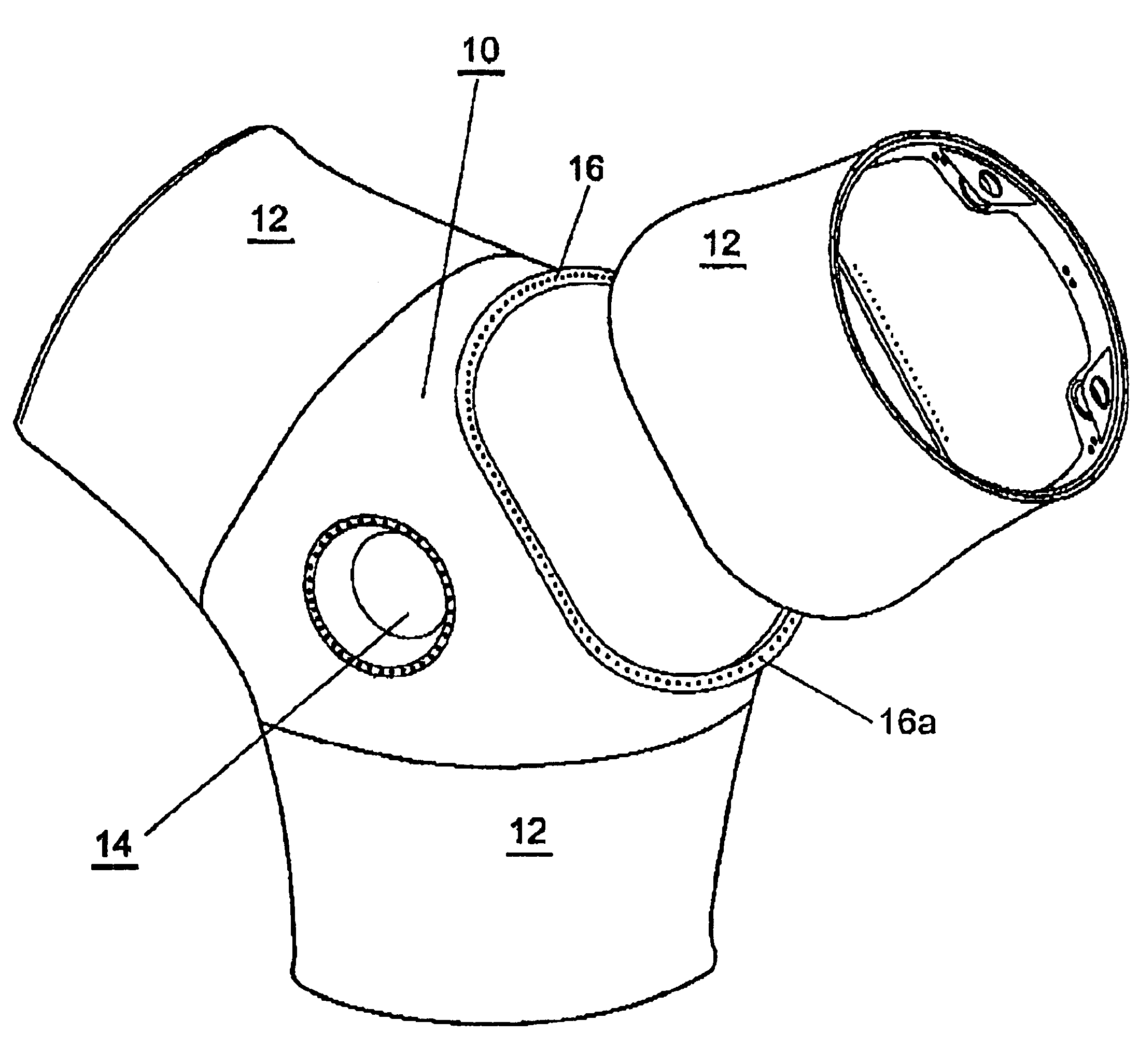
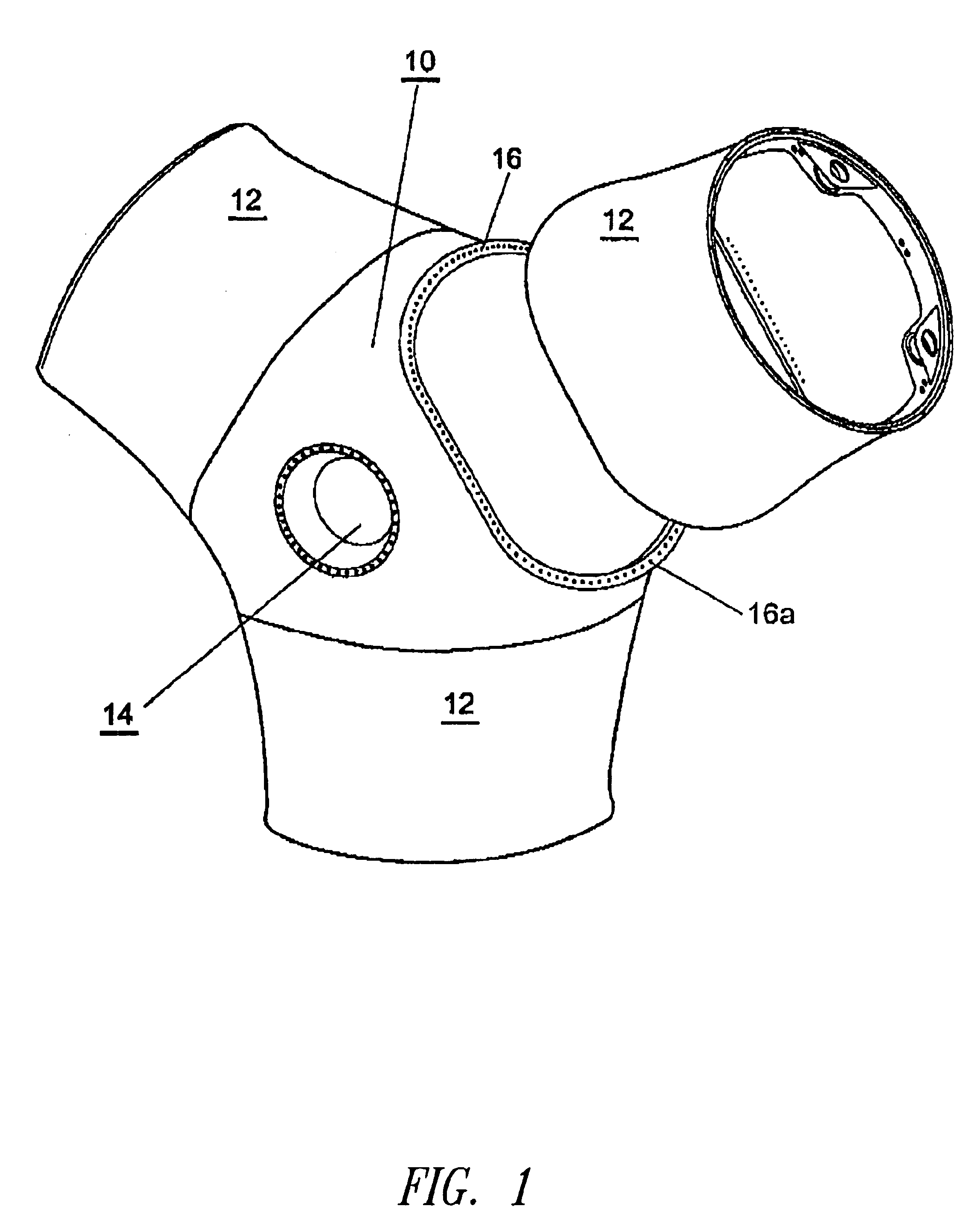
[0021]FIG. 1 shows a hub core 10 (being of a substantially triangular configuration in the view from the front thereof) with a bush 14 for receiving the shaft trunnion (not shown). The rotor blade hub is fitted with that bush 14 on to the rotor shaft (for example the shaft trunnion). Shown at a small distance from the hub core 10 are three outer hub portions 12 which are (and remain) durably fixed to the hub core 10 in the illustrated orientation and to which in turn the rotor blades (not shown) are fixed in known manner (see in that respect: Erich Hau ‘Windkraftanlagen’ [‘Wind Power Installations’]).

[0022]In accordance with a preferred embodiment of the invention FIG. 1 shows a rotor blade hub for carrying three rotor blades. Accordingly the rotor blade hub has three outer hub portions, a respective one for the connection of each rotor blade, and the hub core 10, as a fourth individual piece of the rotor blade hub. This means that the rotor blade hub is formed from a number of indi...


PUM


Abstract

The present invention concerns a rotor blade hub for a wind power installation. Such a hub represents a mechanical connection between the (horizontal) rotor shaft (rotor spindle) and the rotor blades. This means that all forces which occur at the rotor blades, insofar as they are not forces in the rotor blades themselves, also occur at the hub. Besides the (intentional) rotational forces, these involve inter alia also centrifugal forces and forces, loads and moments which arise out of the action of the wind on the rotor blades. Therefore the object of the present invention is to provide a rotor blade hub which, being of the required dimensions, satisfies all demands for reliable and safe operation of a wind power installation and which ensures secure and as inexpensive as possible transportation to the erection site of the wind power installation. A rotor blade hub for a rotor having at least one rotor blade, formed from at least two individual pieces.

Description

BACKGROUND OF THE INVENTION[0001]1. Field of the Invention[0002]The present invention concerns a rotor blade hub for a wind power installation.[0003]2. Description of the Related Art[0004]Such a hub represents a mechanical connection between the (horizontal) rotor shaft (rotor spindle) and the rotor blades. This means that all forces which occur at the rotor blades, insofar as they are not forces in the rotor blades themselves, also occur at the hub. Besides the (intentional) rotational forces, these involve inter alia also centrifugal forces and forces, loads and moments which arise out of the action of the wind on the rotor blades.[0005]The rotor hub is accordingly one of the most highly loaded parts of a wind power installation and, as the connection between the rotor blades and the ‘rest of the installation’, it constitutes the component whose strength must guarantee that no rotor blade can tear away from the installation.[0006]Therefore in the state of the art in most cases rot...

Claims


Application Information

Patent Timeline
Patent Type & Authority Patents(United States)
IPC IPC(8): F03D1/00F03D1/06F03D11/00
CPCF03D1/0658Y02E10/721Y02E10/72F03D1/06
Inventor WOBBEN, ALOYS
Owner WOBBEN ALOYS
Why Eureka
Try Eureka