Cabinet and construction method for its back plate
A backplane and bottomboard technology, which is applied in the construction field of cabinets and their backplanes, can solve the problems of time-consuming and labor-intensive operations for opening 4 holes on the backplane
- Summary
- Abstract
- Description
- Claims
- Application Information
AI Technical Summary
Problems solved by technology
Method used
Image

Examples
Embodiment Construction
[0041] Below in conjunction with accompanying drawing, further illustrate cabinet of the present invention and backboard construction method thereof.
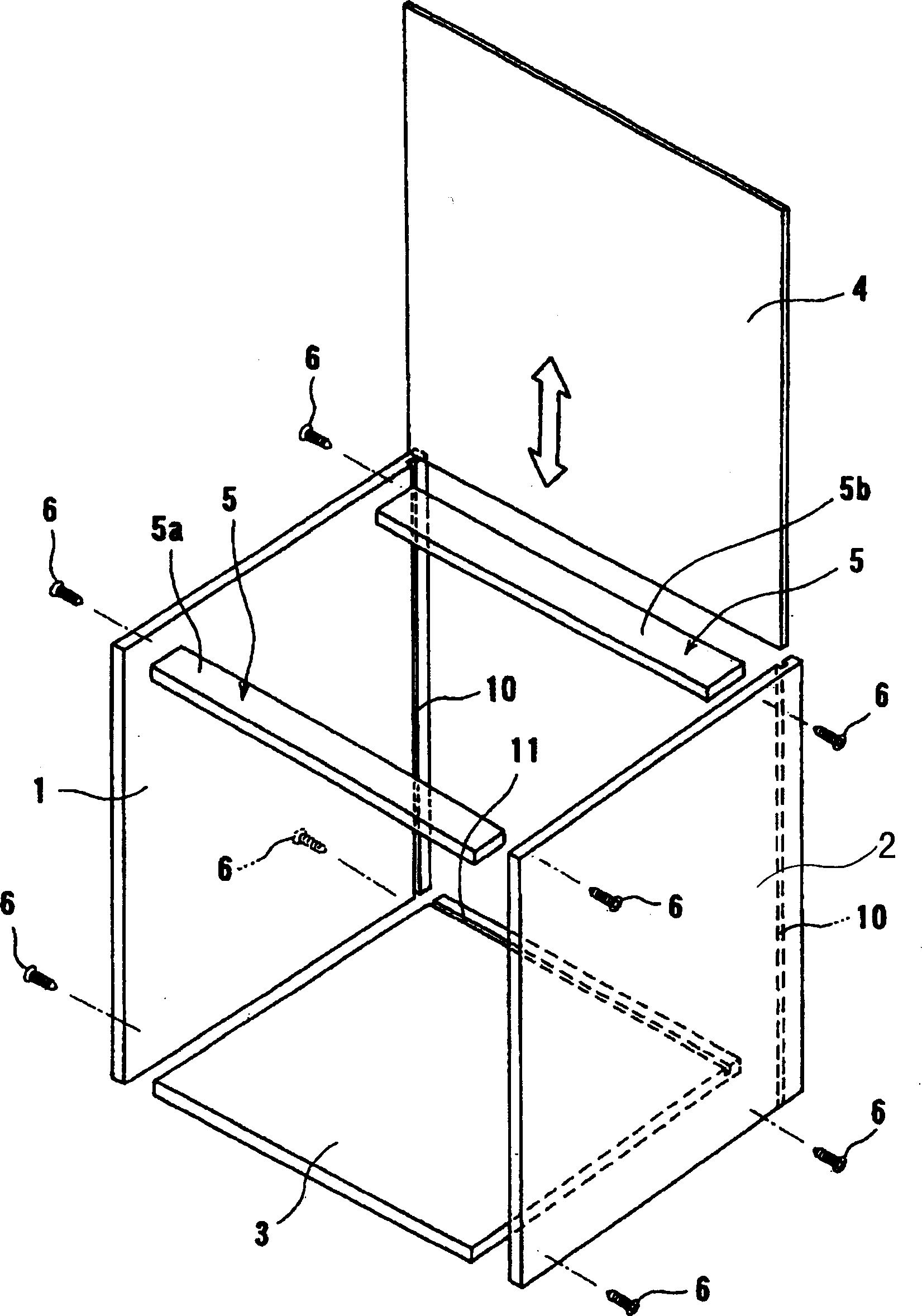
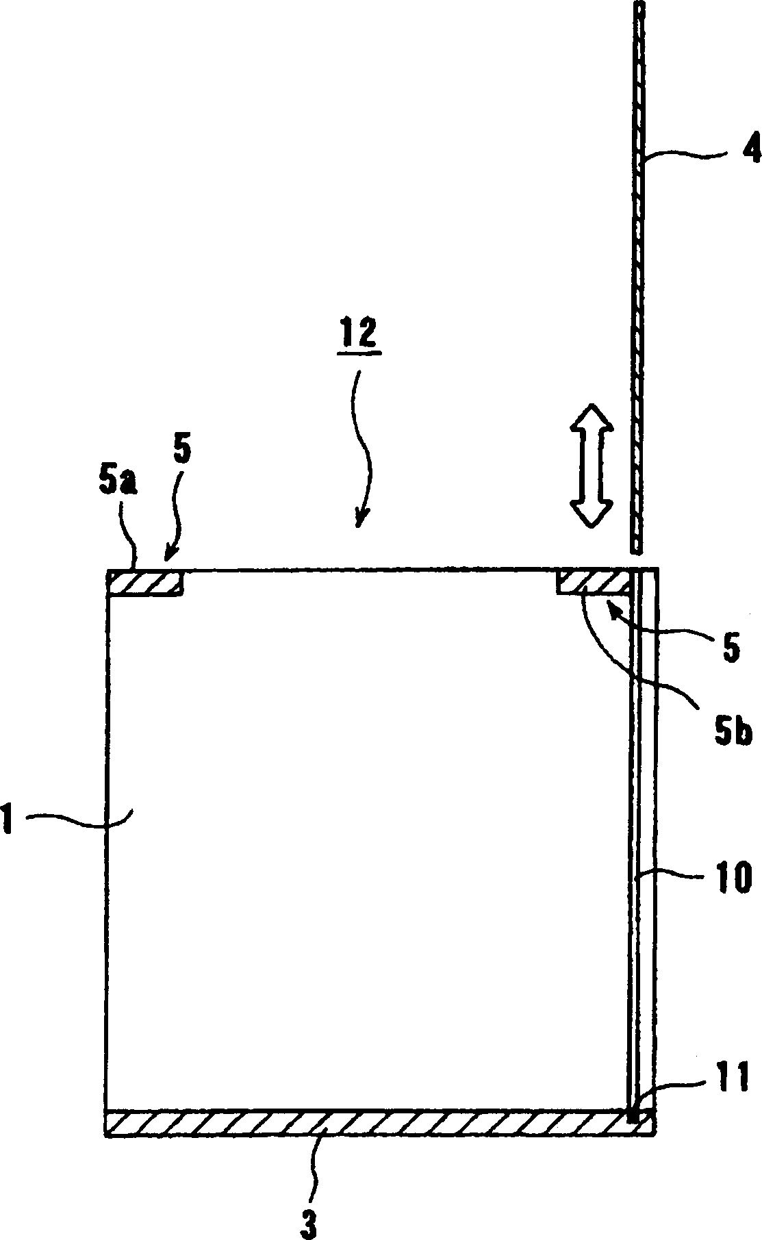
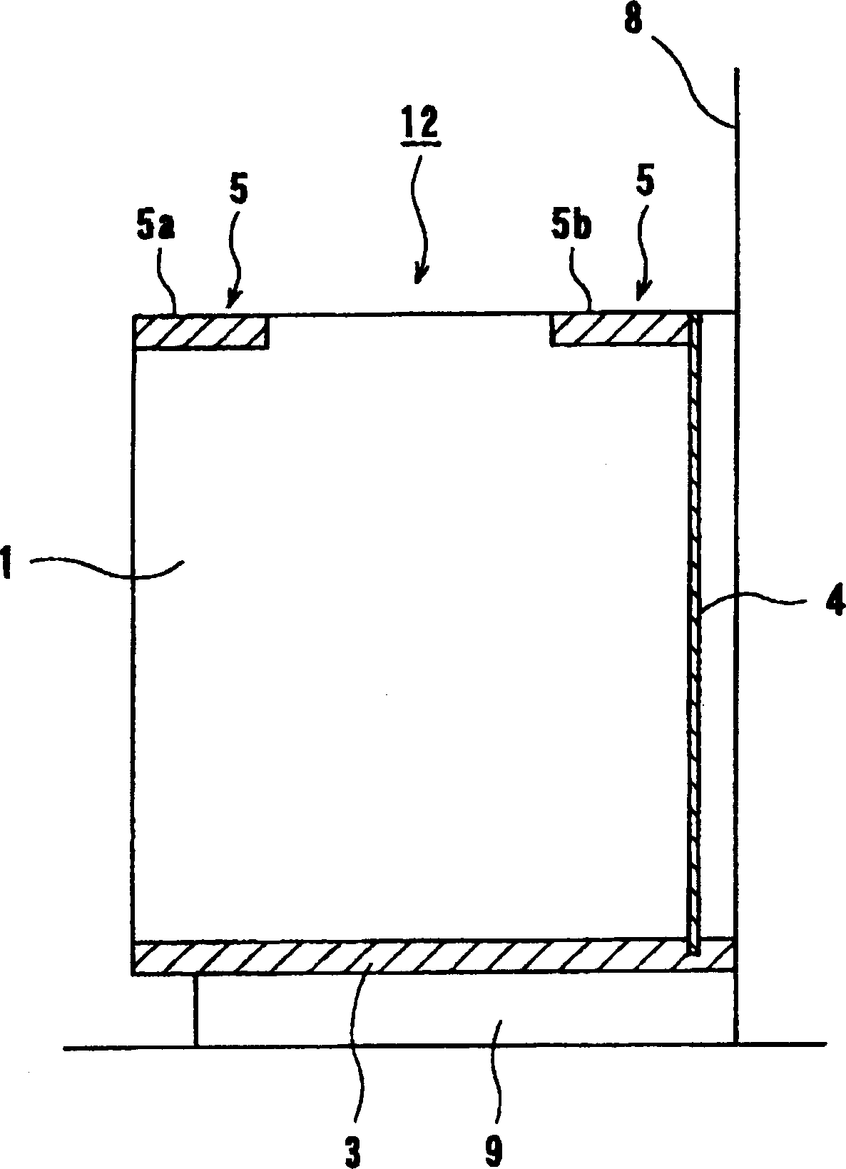
[0042] figure 1 , figure 2 They are respectively an exploded perspective view and a sectional view of an embodiment of the cabinet of the present invention. Such as figure 1 and figure 2 As shown, the cabinet of the present invention will be provided with the left side plate 1 and the right side plate 2 of the vertical groove 10 along the full length of the longitudinal direction at the rear end, and the bottom plate provided with the transverse groove 11 along the full length of the transverse direction at its rear end is separated 3, and make the faces forming the vertical grooves 10 face each other, and at the same time make the vertical grooves 10 and the horizontal grooves 11 communicate. An upper part 5 is arranged between the upper ends of the left and right side plates 1, 2. In this embodiment, the upper part 5 ...
PUM
 Abstract
Description
Claims
Application Information
PatSnap Eureka turns technology decisions into work you can execute. Powered by our Innovation Knowledge Graph, it runs expert workflows across engineering, life sciences, materials and intellectual property. Get your review-ready output in minutes.


